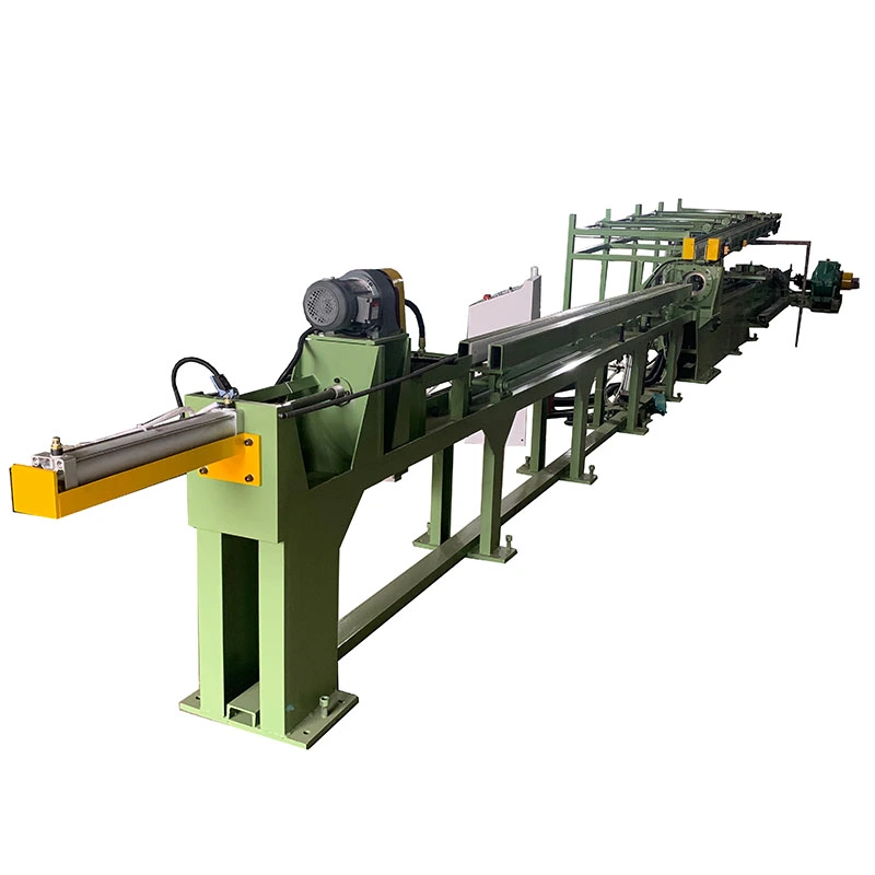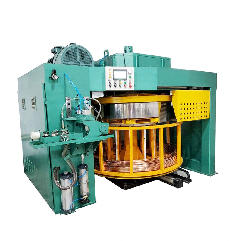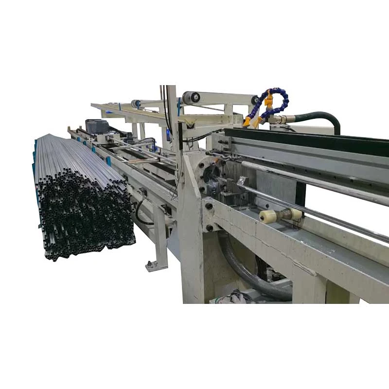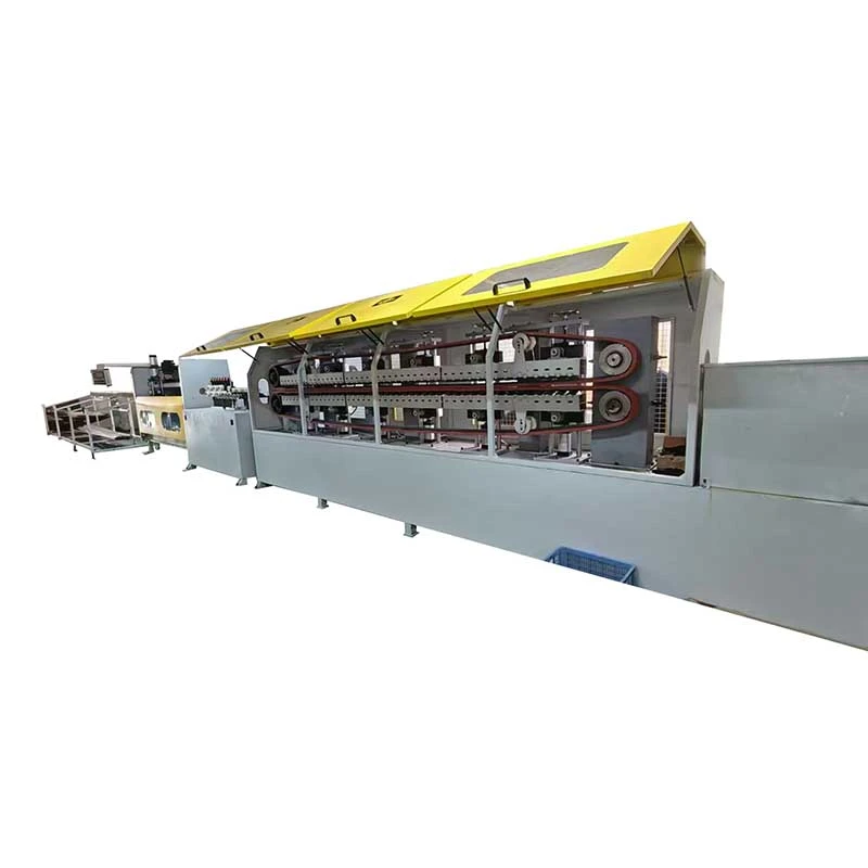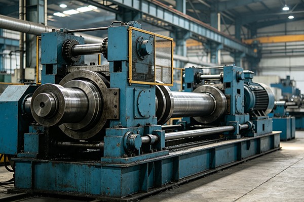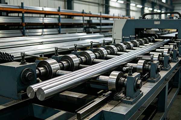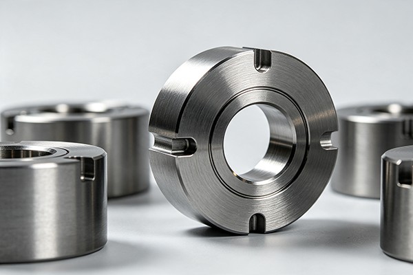

We offer a comprehensive range of precision metal processing equipment, including straightening, cold drawing, pointing, chamfering, cutting, thread rolling machines, and drawing dies, tailored for tube, bar, and wire materials across diverse industries.
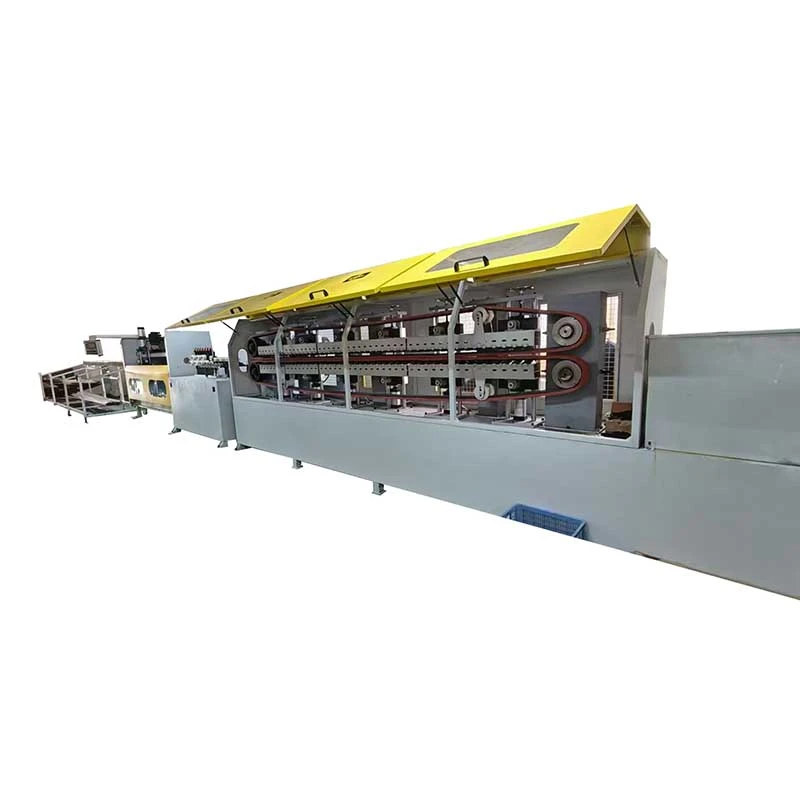
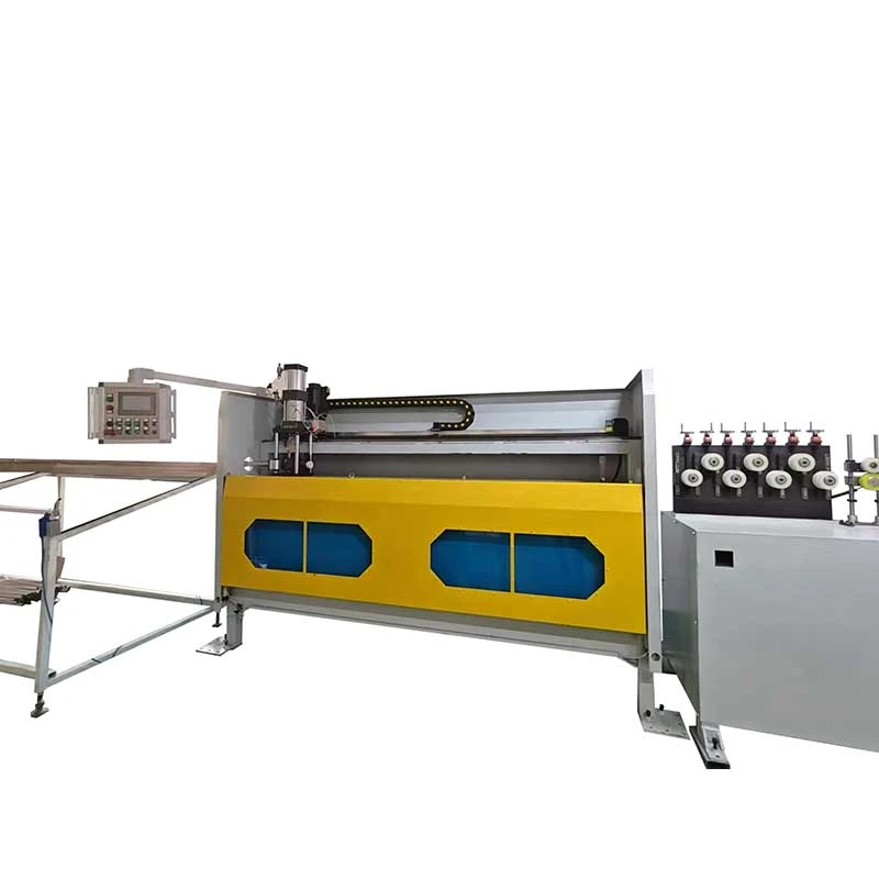
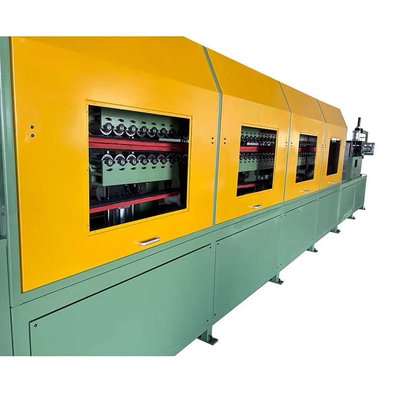
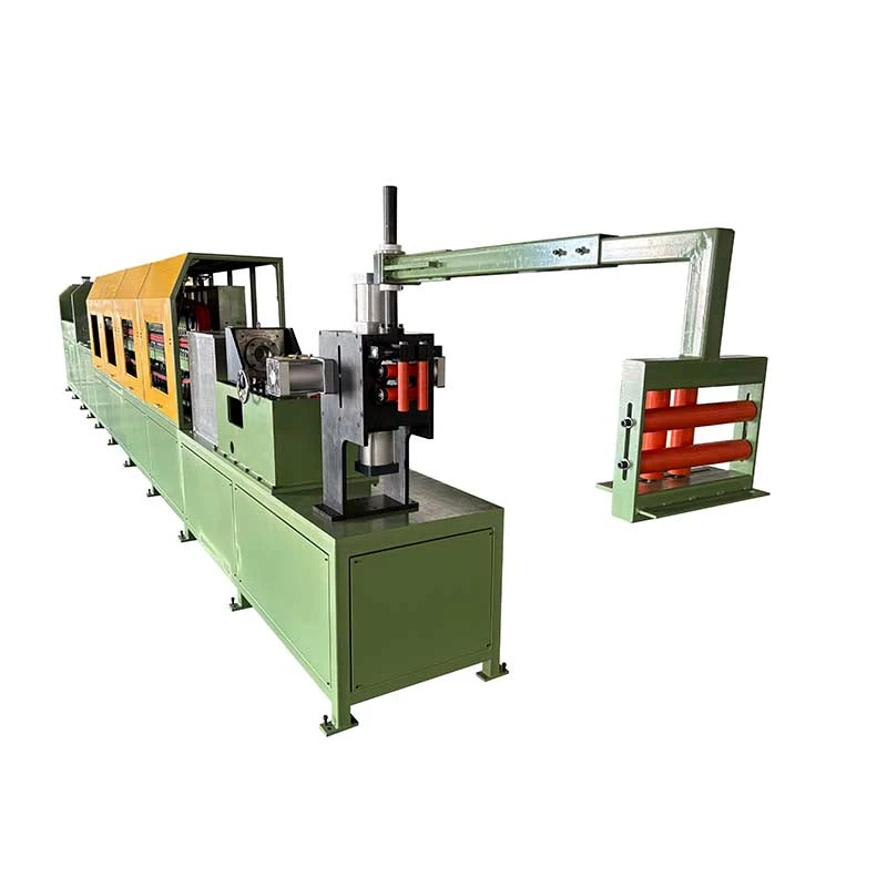
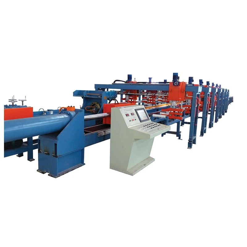
The Automatic Crawler-Type Cold Drawing Machine to Coil is designed for continuous drawing and coiling of small-diameter metal tubes. With drawing forces of 10–50 kN and speeds up to 100 m/min, the crawler-track drive provides stable pulling and continuous operation. It handles tube diameters of φ5–40 mm and feeds drawn material directly into the coiler, reducing cutting, handling, and storage. Suitable for copper, aluminum, stainless steel, and carbon steel tubes used in HVAC, automotive, electrical, and general engineering.
The Automatic Crawler-Type Cold Drawing Machine to Coil is designed for manufacturers that need to draw small-diameter metal tubes continuously and receive the finished product in coils instead of straight lengths. It combines a crawler-type drawing system, precision die holder, PLC control and automatic coiling station in one production line, eliminating repeated stopping, unloading, cutting and manual transfer between drawing and coiling operations.
This configuration is particularly useful when the product is supplied in long continuous lengths for downstream tube bending, cutting, heat-exchanger manufacturing or further drawing. The FR series covers tube diameters from φ5 to φ40 mm, with drawing forces from 10 to 50 kN and maximum drawing speeds of 80-100 m/min, depending on the model and process conditions.
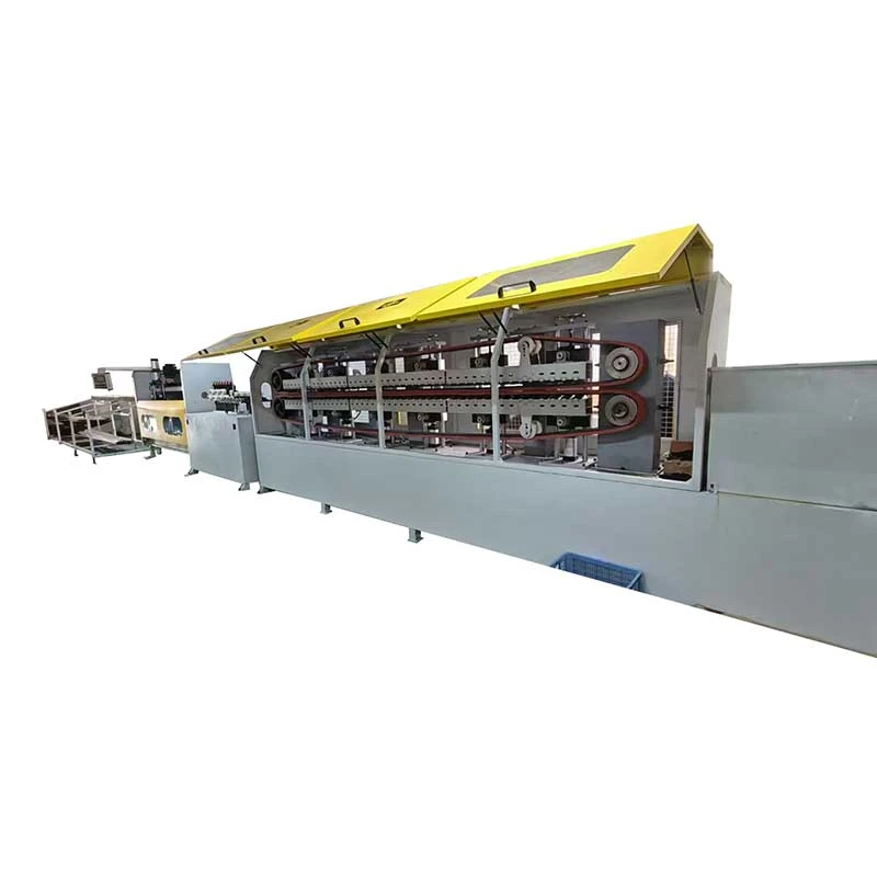
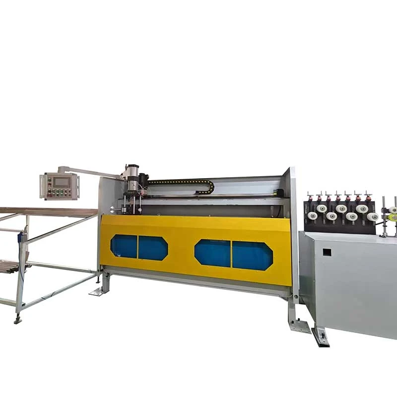
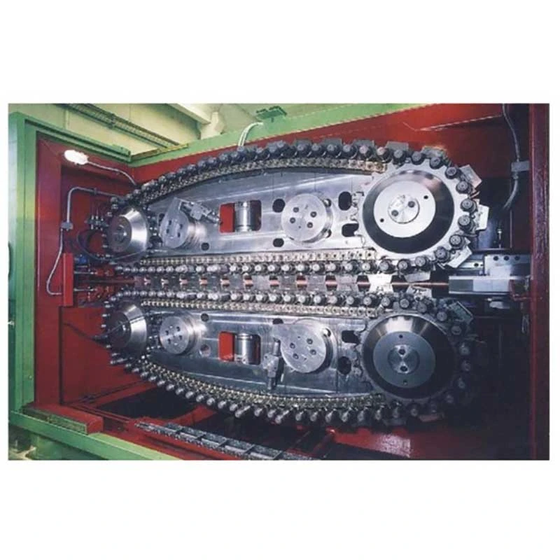
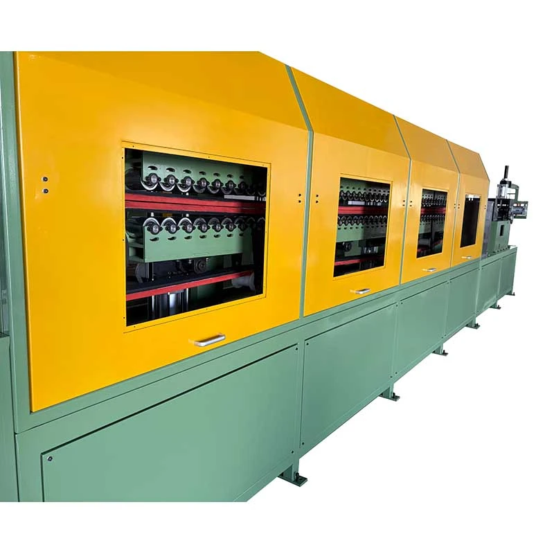
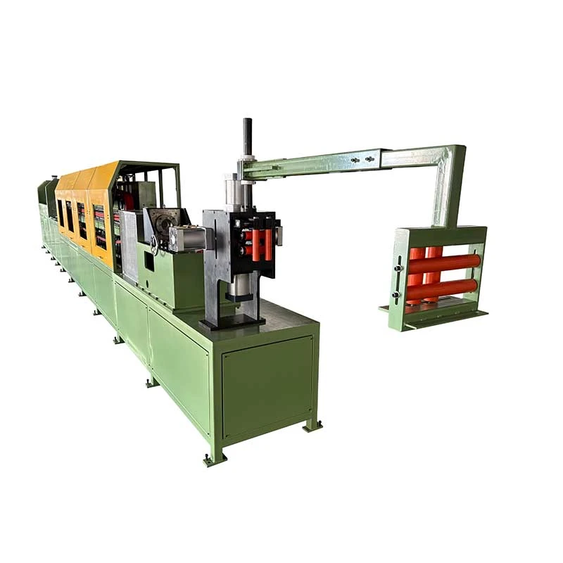
Traditional chain or hydraulic drawbenches pull the tube in individual strokes. The Automatic Crawler-Type Cold Drawing Machine to Coil must stop after each stroke so the operator can reset, unload or transfer the workpiece. This operating method is acceptable for short straight tubes, but it becomes inefficient when the customer needs hundreds or thousands of metres of continuous small-diameter tubing.
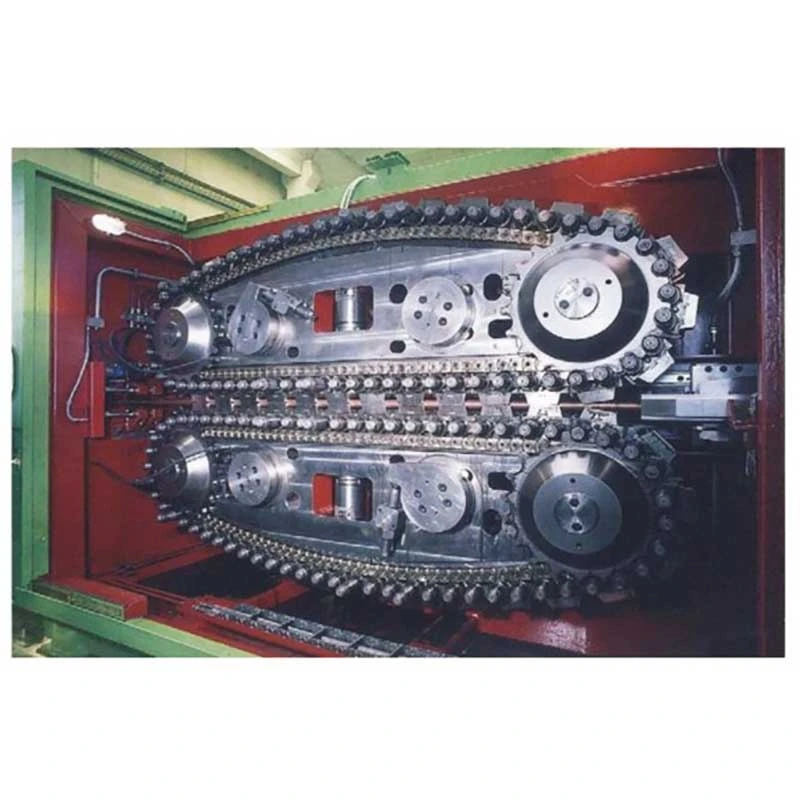
The crawler system changes the pulling method from intermittent stroke movement to continuous friction pulling. Upper and lower crawler tracks grip the tube over a long contact area and continuously feed it through the drawing die. The finished tube then enters the coiler directly.
The result is not simply a higher drawing speed. The main production advantages are fewer handling steps, less intermediate storage, reduced operator intervention and a finished product format that can be transferred directly to the next process.
When continuous drawing matters: It is most valuable for long-length copper, aluminium and steel tubing where production volume and coil delivery are more important than producing individual straight bars.
When it matters less: If your product is always supplied as short straight lengths and requires frequent changes between very different tube sizes, a conventional drawbench may be more appropriate. Machine selection should therefore be based on material, reduction per pass, finished diameter, required length and delivery format rather than speed alone.
1. Tube feeding: The incoming tube is supplied from a decoiler or straight-length feeding system and enters the machine through the entry guide.
2. Drawing die: The tube passes through a precision drawing die, reducing the outside diameter and controlling the finished dimensional profile. Die design and lubrication have a direct effect on drawing force, surface condition and tool life.
3. Continuous crawler pulling: Two parallel crawler tracks grip the tube before or around the drawing operation. Multiple pairs of pneumatic cylinders apply controlled pressure to maintain friction between the tracks and tube. Unlike a chain drawbench, the crawler does not need to release and reset after each stroke.
4. Variable-speed drawing: Drawing speed is continuously adjustable within the rated range. The actual production speed should be selected according to material strength, tube size, reduction ratio, lubrication and required surface finish rather than simply operating at maximum speed.
5. Synchronized coiling: The drawn tube enters the coiling station immediately after leaving the drawing section. Coiling speed follows the drawing speed to control line tension and produce a stable coil.
6. Coil change: When the preset coil length or production quantity is reached, the control system stops the line for coil replacement and the next spool or drum can be positioned for production.
7. PLC and HMI control: The control system manages drawing speed, length counting, coiling operation and coil-change sequencing, allowing the operator to monitor the complete process from one control station.
The crawler drive provides continuous pulling instead of repeated pull-stop cycles. FR-16 and FR-25 offer drawing speeds up to 80 m/min, while FR-38 reaches up to 100 m/min.
For a high-volume copper tube producer supplying long coils to HVAC manufacturers, this operating principle can remove the downtime associated with repeated drawbench strokes. However, maximum speed is not automatically the best production speed. For difficult stainless steel grades or high reduction ratios, a lower speed with appropriate lubrication may provide better tool life and surface quality.
The crawler contact length ranges from 1800 to 3500 mm. A longer contact area allows the drawing force to be distributed over a greater tube length, reducing the risk of crawler slipping when higher pulling force is required.
This parameter becomes particularly important when processing harder materials, larger tube diameters or higher reductions. For soft copper tube with a modest reduction, the longest crawler is not necessarily required.
The FR series uses multiple air-cylinder pairs to control crawler clamping pressure. FR-16 uses 8 pairs, FR-25 uses 10 pairs and FR-38 uses 12 pairs.
The purpose is to maintain sufficient frictional grip along the drawing zone without relying on excessive pressure at a single point. Correct pressure adjustment is important because insufficient pressure can cause slipping, while excessive pressure can mark or deform the tube surface.
The finished tube is wound directly onto a spool or drum after drawing. This is useful for HVAC, refrigeration and automotive tubing where downstream processes often require long continuous material.
A copper tube producer using an FR-38 for air-conditioning tubing can therefore transfer the finished coil directly to subsequent cutting, bending or heat-exchanger production instead of first cutting the material into straight lengths, bundling it and then feeding it into another process.
The three standard models cover different diameter and drawing-force requirements. Selecting a larger model simply because it offers a higher maximum speed can increase equipment and energy costs without improving production if the required tube size and reduction are small.
| Model | FR-16 | FR-25 | FR-38 |
| Tube Diameter Range | φ5-φ16 mm | φ10-φ25 mm | φ10-φ40 mm |
| Drawing Force | 10 kN | 30 kN | 50 kN |
| Main Motor Power | 15 kW | 22 kW | 37 kW |
| Drawing Speed | 0-80 m/min | 0-80 m/min | 0-100 m/min |
| Air Cylinder Pairs | 8 pairs | 10 pairs | 12 pairs |
| Crawler Width | 80 mm | 100 mm | 120 mm |
| Crawler Contact Length | 1800 mm | 2500 mm | 3500 mm |
| Coiling Station | Integrated | Integrated | Integrated |
Model selection: FR-16 is suited to smaller tube sizes up to φ16 mm; FR-25 provides a higher drawing force for φ10-φ25 mm applications; FR-38 is intended for larger tube sizes up to φ40 mm and applications requiring up to 50 kN drawing force. Final selection should be confirmed from the starting diameter, finished diameter, material grade, reduction per pass, lubrication method and required production output.
Typical materials: Copper and aluminium tubes for air-conditioning coils, refrigeration systems, condensers and evaporators.
Customer scenario: A copper tube manufacturer uses an FR-38 crawler drawbench with integrated coiling to produce long air-conditioning tubing. The continuous drawing process allows the drawn tube to enter the coiler directly, reducing the need for intermediate cutting and manual transfer before the next production operation.
For this application, drawing speed and coil stability are usually more important than maximum drawing force alone. Lubrication, die condition and final dimensional tolerance should be evaluated together with output requirements.
Typical materials: Carbon steel, stainless steel, copper and aluminium tubing for brake lines, fuel systems and vehicle air-conditioning systems.
Customer scenario: An automotive tubing supplier uses an FR-25 for continuous production of coiled small-diameter tubing. The crawler pulling system avoids the repeated acceleration and deceleration associated with intermittent drawing, helping the producer maintain a more stable continuous process before downstream cutting and forming.
For automotive tubing, surface condition and dimensional consistency may be more important than achieving the highest possible line speed because defects can become costly after bending, flaring or assembly.
Typical materials: Stainless steel and other precision alloys used for small-diameter tubing and instrumentation components.
Customer scenario: A medical-device manufacturer uses an FR-16 to draw small-diameter stainless steel tubing for subsequent cutting and assembly. The continuous process is suitable when long, consistent tube lengths are required before the material is cut into individual components.
For medical and instrumentation applications, maximum speed is usually less important than dimensional control, surface condition, tooling stability and traceable quality inspection.
Small copper, aluminium and steel tubes can be drawn and coiled for electrical components, instrumentation, heat-transfer components and other engineered products. The integrated coiling configuration is most useful where the next process can accept continuous coil material.
The standard machine package includes the crawler drawing system, main motor, gearbox, die holder, pneumatic clamping system, integrated coiling station, PLC control cabinet with HMI and standard machine components.
Drawing dies for specific tube sizes are normally selected according to the customer's material and pass schedule and can be quoted separately. Decoilers, additional feeding equipment, special coiling drums, customized automation and other upstream or downstream equipment can be configured according to the production line.
| MOQ | 1 complete machine set |
| Quantity-Based Pricing | 1 set / 2-4 sets / 5+ sets; final unit price is quoted according to model, configuration and order quantity |
| Trade Term | FOB Shenzhen Port, China; other Incoterms available by agreement |
| Payment Term | 30% deposit after order confirmation; 70% balance before shipment after factory acceptance test |
| Standard Order Lead Time | FR-16 / FR-25: approximately 30-60 days; FR-38 and customized configurations: approximately 60-90 days |
| Expedited Order | Priority production can be arranged according to factory capacity and configuration. The accelerated delivery date must be confirmed in the commercial quotation before order placement. |
| Warranty | 12 months from commissioning |
Important: Lead time starts after technical specifications, drawing requirements and commercial terms are confirmed. Custom dies, special automation, imported electrical components and customer-specific testing requirements may affect the final delivery schedule.
The Automatic Crawler-Type Cold Drawing Machine to Coil is engineered around the customer's actual tube drawing process rather than selected only by nominal tube diameter. Before production, the technical team can evaluate the material grade, starting size, finished size, reduction ratio, required drawing force, production speed and coiling requirements.
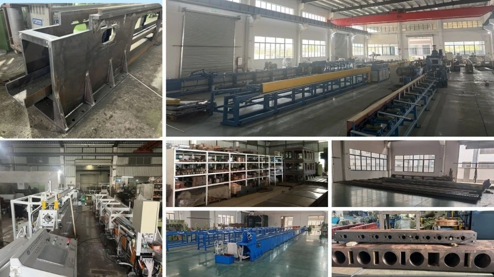
1. Process engineering: Confirm tube material, dimensions, die arrangement, crawler configuration and coiling requirements.
2. Material inspection: Inspect key steel, shafts, gears, crawler components and other load-bearing parts before machining.
3. Precision machining: Machine crawler frames and major mechanical components according to engineering drawings and required tolerances.
4. Mechanical assembly: Assemble crawler drive, gearbox, pneumatic clamping system, die holder and coiling system.
5. Electrical integration: Install PLC, HMI, sensors, motors and control components and complete machine wiring.
6. PLC commissioning: Verify drawing-speed control, length counting, coiling synchronization and coil-change sequence.
7. Factory testing: The machine is subjected to idle running and load testing. Where customer tube samples are available, drawing and coiling performance can be checked using the actual material.
8. Final inspection: Check machine dimensions, electrical functions, pneumatic operation, lubrication, safety devices and finished coil condition.
9. Export packaging: The machine is packed according to overseas transportation requirements, with protection against moisture, corrosion and handling damage.
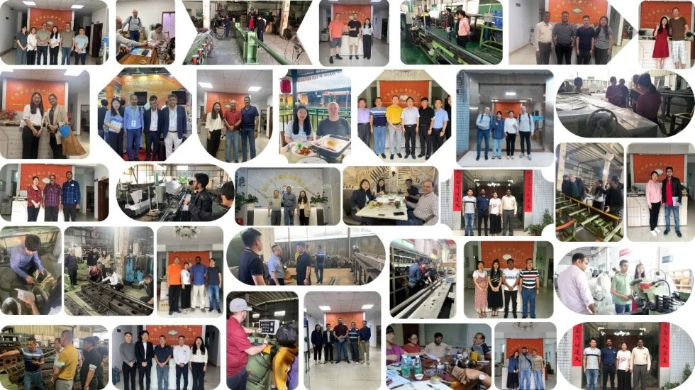
Drawbench engineering since 1998. FangRong has focused on cold drawing and related metal forming equipment for more than two decades. The company's engineering background includes a Taiwanese drawing-equipment partnership and subsequent independent manufacturing development.
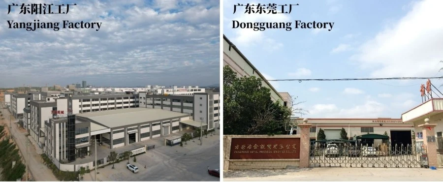
Two manufacturing facilities. Dongguan and Yangjiang production facilities support mechanical fabrication, assembly, testing and equipment delivery for different order volumes.
International installation experience. FangRong equipment has been supplied to customers in more than 70 countries, providing practical experience with different tube materials, production requirements and factory conditions.
Factory acceptance testing. Key operating functions are checked before shipment. For projects where customer samples are supplied in advance, the drawing and coiling process can be tested against the actual production material.
Application-based engineering support. The technical team can assist with die selection, drawing-force calculation, pass-schedule planning, crawler configuration, machine layout and coiling requirements. This is particularly important when replacing an intermittent drawbench with a continuous drawing line.
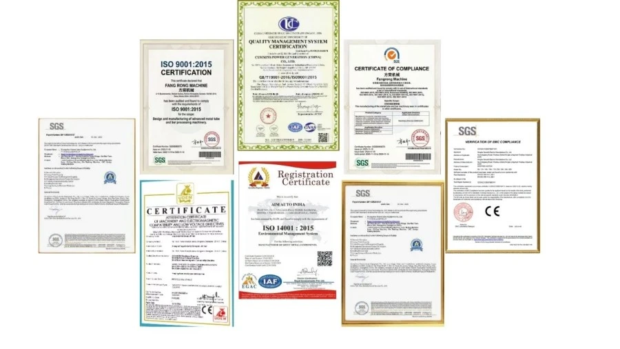
ISO 9001:2015 — Quality management system covering design, production, installation and service. Certificate No. UQ231211R1.
CE Marking — Standard FR machines are supplied with CE conformity documentation applicable to the machine configuration and relevant EU requirements. Machinery safety assessment is based on applicable requirements of Directive 2006/42/EC and associated harmonized standards.
SGS Inspection — Third-party inspection can be arranged for agreed machine specifications, performance and safety requirements.
Patent portfolio — FangRong has developed patented technologies relating to drawing equipment, die holders, tensioning mechanisms and other metal-forming components.
Note: CE conformity is configuration-specific. If the machine will be imported into the EU, the final technical file, declaration of conformity, safety devices and electrical configuration should be confirmed for the exact machine supplied. UKCA documentation and other market-specific requirements can be discussed before production.
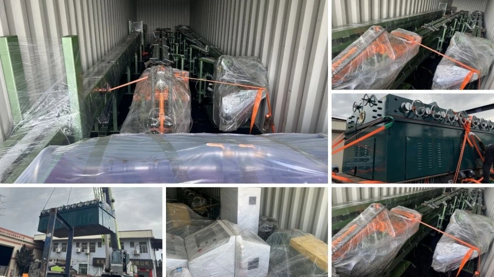
The Automatic Crawler-Type Cold Drawing Machine to Coil is prepared for international shipment with export-oriented packaging and protection for mechanical, electrical and pneumatic components. The final packing method depends on machine dimensions, shipping route and whether the equipment is shipped as a complete machine or in separated sections.
For overseas projects, the packing list, machine dimensions, gross weight and loading arrangement are confirmed before shipment so the buyer can prepare customs clearance, inland transportation and factory unloading equipment in advance.
Start with the actual tube diameter and drawing force rather than maximum speed. FR-16 covers φ5-φ16 mm and provides 10 kN; FR-25 covers φ10-φ25 mm and provides 30 kN; FR-38 covers φ10-φ40 mm and provides 50 kN. Material strength, starting diameter, finished diameter and reduction per pass should also be considered.
Yes, the FR series can be configured for copper, aluminium, stainless steel, carbon steel and selected specialty alloys. However, the same machine should not be assumed to use identical dies, lubrication or drawing parameters for every material. Harder materials generally require more drawing force and closer control of reduction and lubrication.
No. 100 m/min is the maximum rated speed of FR-38 under suitable process conditions. Actual production speed depends on material, tube dimensions, reduction, die design, lubrication, surface requirements and coiling conditions. Running at the maximum speed is useful only when the complete process can maintain stable quality at that speed.
The main difference is the pulling method. A conventional drawbench pulls in strokes, while the crawler system provides continuous friction-based pulling. This is advantageous for long continuous tubes because it reduces stop-start cycles and allows the drawn product to enter the coiler directly.
Proper crawler pressure, track condition, alignment and process lubrication are important. Excessive clamping pressure can damage sensitive surfaces, while insufficient pressure can cause slipping. The clamping system therefore needs to be adjusted according to tube material and surface requirements rather than simply applying maximum pressure.
Please provide the material grade, starting tube diameter, finished diameter, tube wall thickness if applicable, required drawing speed, target production output, coil dimensions and available power supply. A drawing sample or existing pass schedule is also useful. These parameters allow the required drawing force and machine model to be checked before quotation.
The standard machine includes the drawing system and die holder. Dies for specific tube sizes are selected according to the customer's material and dimensions and are normally quoted according to the required drawing process.
Yes. The FR-series configuration includes an integrated coiling station. The coiler follows the drawing line speed and winds the finished tube onto the specified spool or drum. Coil length, tension and changeover requirements should be confirmed during technical specification.
The standard MOQ is 1 complete machine set. Quantity-based quotations can be prepared for 1 set, 2-4 sets and 5+ sets. The final unit price depends not only on quantity but also on the selected model, tooling, coiling configuration, automation and customer-specific requirements.
The standard FOB quotation is based on Shenzhen Port, China. If your logistics arrangement requires another Chinese port, the shipping term and inland transportation cost can be recalculated in the quotation.
Standard FR-16 and FR-25 orders generally require 30-60 days. FR-38 and machines with customized configurations generally require 60-90 days. The confirmed lead time starts after technical specifications and order details are finalized.
Priority production can be discussed for urgent projects. An expedited order is subject to current factory capacity, component availability and machine configuration. The accelerated delivery date should be confirmed in writing in the commercial quotation before the order is placed.
The standard payment arrangement is 30% deposit after order confirmation and 70% balance before shipment after factory acceptance testing. Alternative terms can be discussed for qualified projects.
The machine is checked for mechanical operation, electrical functions, pneumatic clamping, drawing-speed control, coiling synchronization, safety functions and overall assembly. When customer tube samples are provided, actual drawing and coiling tests can be arranged before shipment.
Yes. FangRong can provide installation guidance, commissioning support and operator training. Training can cover machine operation, die changing, routine maintenance, crawler adjustment and basic fault diagnosis. The exact service arrangement is confirmed according to the project and destination.
The standard warranty period is 12 months from commissioning. Common replacement parts such as crawler components, gears, seals and sensors can be supplied according to the machine configuration. Remote technical support is also available for operating and maintenance issues.
Yes, where the customer can provide representative tube material and the required drawing information in advance. Testing with the actual material is particularly useful for new applications because it allows drawing force, speed, lubrication, surface condition and coiling performance to be evaluated before delivery.
The buyer should prepare the required foundation, anchor positions, electrical power supply, compressed air, lubrication system and material handling equipment according to the final machine layout. FangRong can provide foundation drawings, anchor-bolt information and installation requirements before shipment.
Address
NO.163,Shatong Road,Shabu 2nd Industrial Zone, Dalang Town, Dongguan City, Guangdong, China