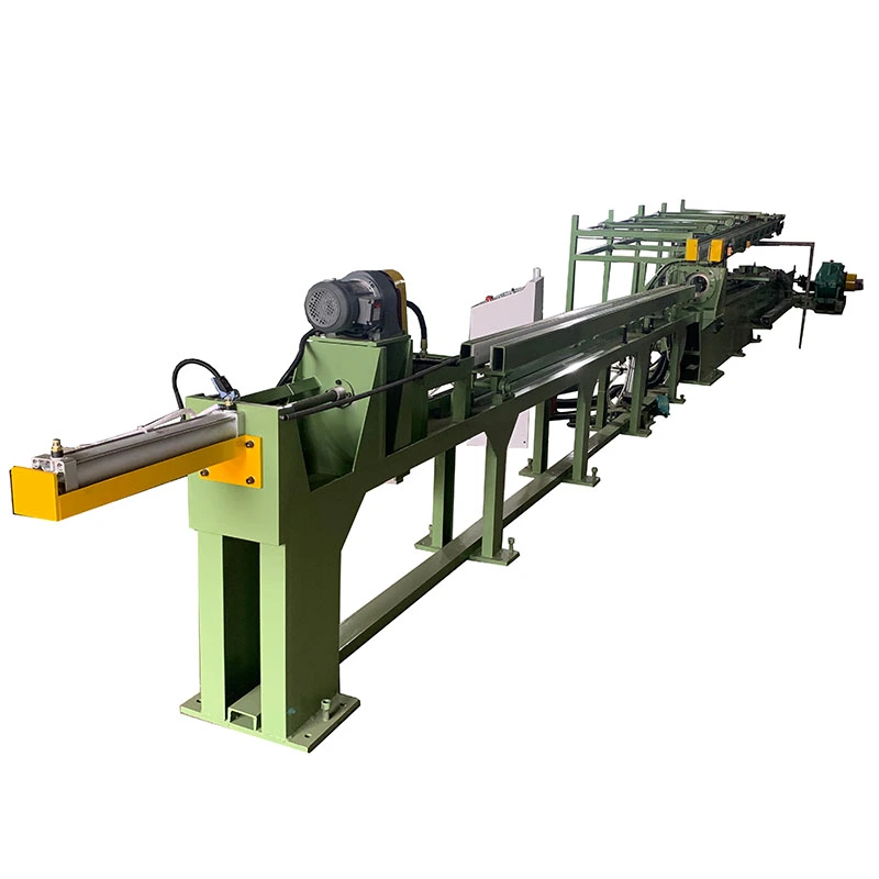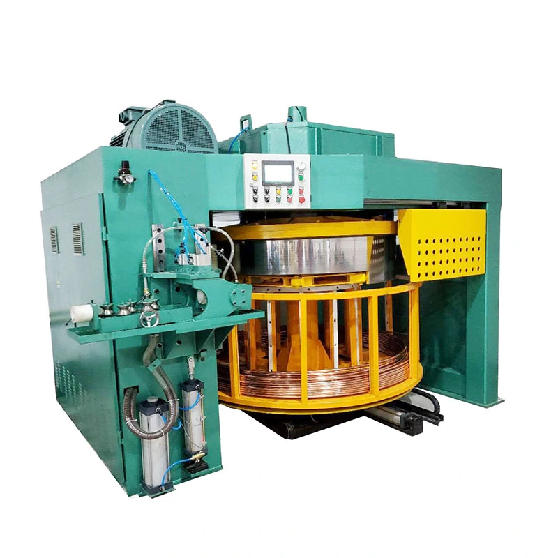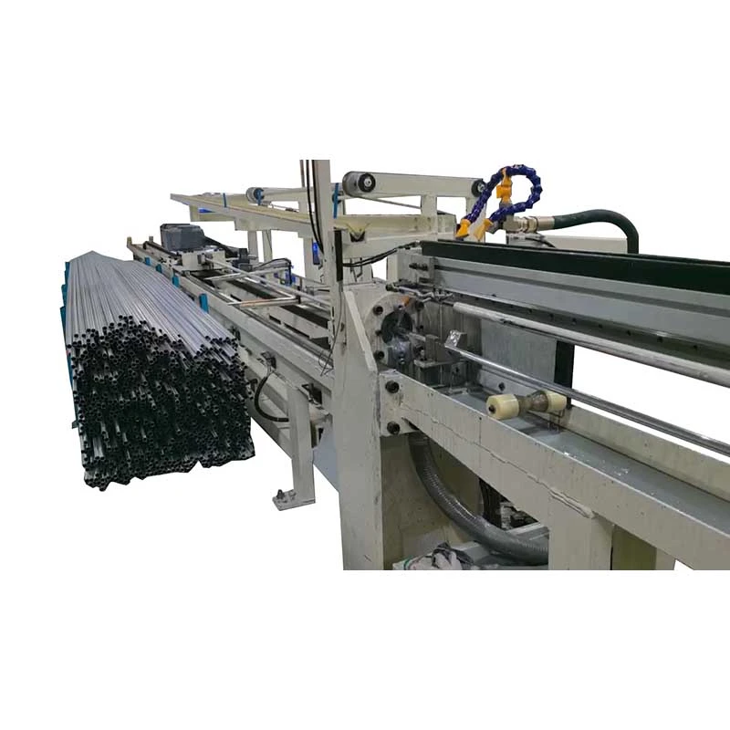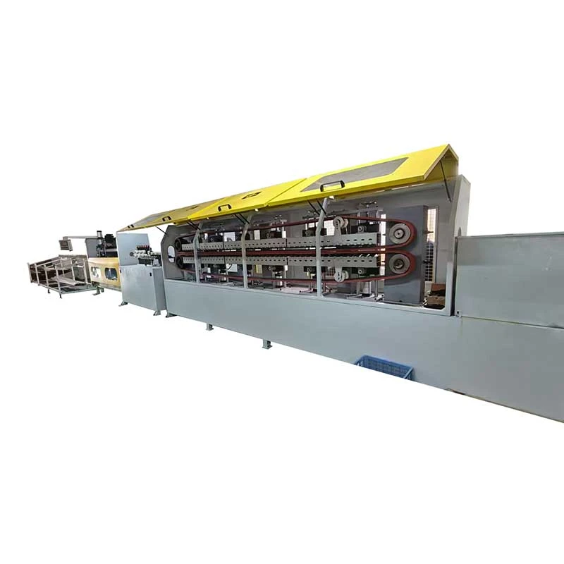
We offer a comprehensive range of precision metal processing equipment, including straightening, cold drawing, pointing, chamfering, cutting, thread rolling machines, and drawing dies, tailored for tube, bar, and wire materials across diverse industries.
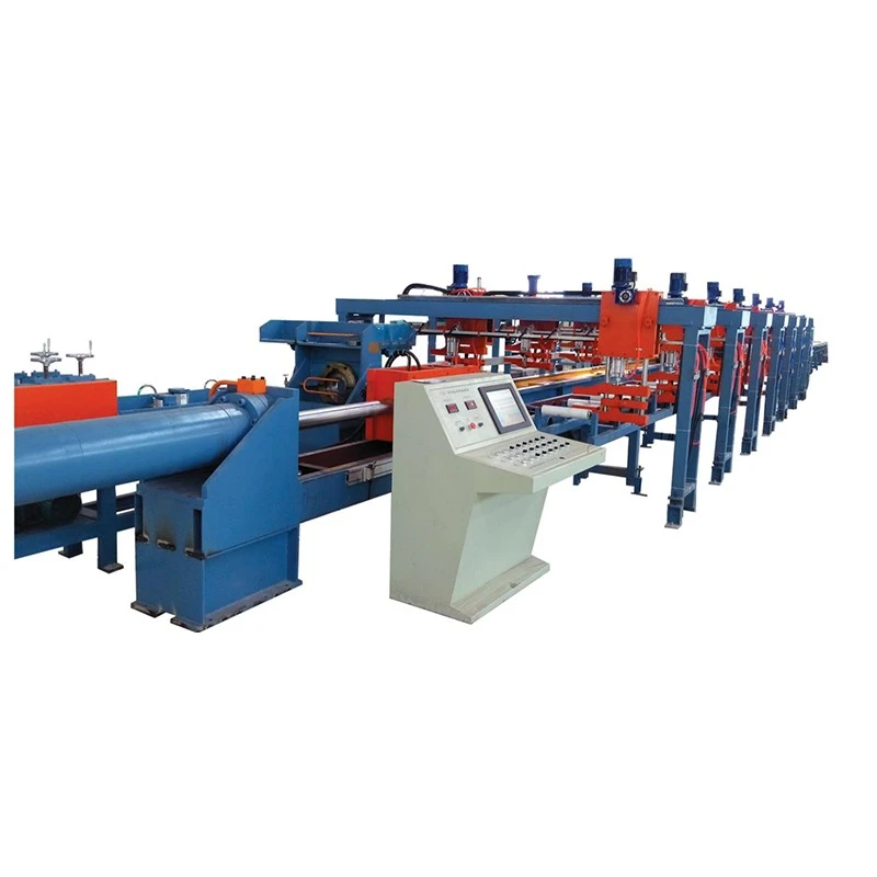
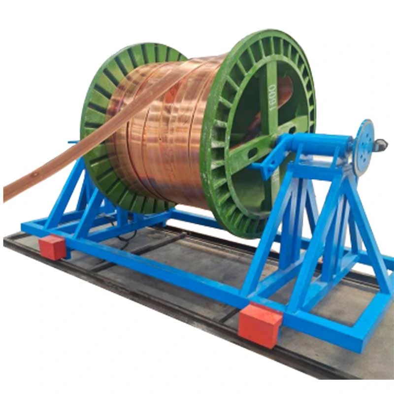
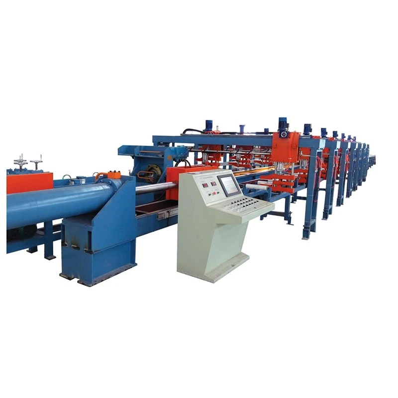
The Busbar Hydraulic Drawing Machine is designed for cold drawing copper and aluminum busbars, improving dimensional accuracy, surface finish, and hardness. Drawing forces range from 10–100 tons, with drawing lengths of 6–12 m and speeds of 2–12 m/min. It handles copper busbars from 40×2 mm to 400×30 mm. Hydraulic force control and variable speed provide stable drawing with reduced surface defects. Suitable for power distribution, transformers, switchgear, and electrical equipment.
The Busbar Hydraulic Drawing Machine, also called a copper busbar drawbench or hydraulic busbar drawing machine, is designed for cold drawing copper and aluminum flat bars after extrusion or casting. The hydraulic cylinder pulls the workpiece through a precision die to reduce width and thickness, improve dimensional consistency, refine the surface, and increase strength through cold work.
FangRong's FR-series includes FR-10T, FR-20T, FR-30T, FR-50T and FR-100T, covering drawing forces from 10 to 100 tons. Depending on the model, the machine handles busbars from 15 to 400 mm in width, 2 to 30 mm in thickness, and 6 to 12 m in effective drawing length. It is mainly used for copper and aluminum busbars for switchgear, distribution equipment, transformers, electrical connectors and other power applications.

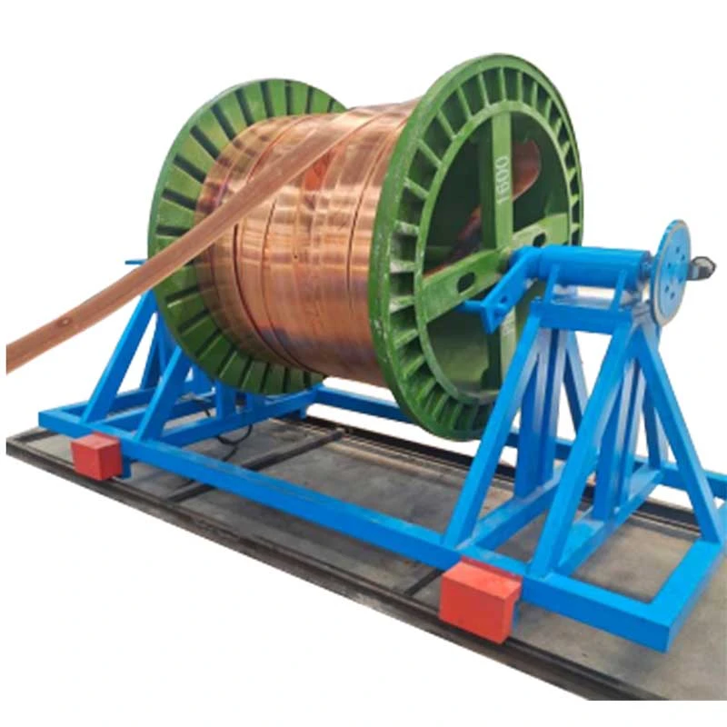
The Busbar Hydraulic Drawing Machine uses a hydraulic pull-through process. The actual die design, reduction per pass and drawing force should be determined from the starting section, target section, material condition and required properties rather than from busbar size alone.
1. Workpiece loading
The extruded or cast copper or aluminum busbar is positioned on the feed rack. The leading end is pointed or reduced so that it can enter the drawing die.
2. Die entry
The prepared end passes through a die designed for the required final cross-section. For non-standard busbar profiles, the die holder and tooling can be configured to match the section.
3. Hydraulic drawing
The hydraulic cylinder pulls the busbar through the die at a controlled force. Cylinder bore sizes across the FR-series range from 125 to 280 mm, with piston rod diameters from 70 to 140 mm.
4. Drawing speed control
Drawing speed is adjustable from 2 to 12 m/min. A lower speed may be preferable for large reductions, difficult sections or process conditions requiring closer control, while stable production lines can use a higher setting where the tooling and lubrication system allow it.
5. Return stroke
After the drawing stroke, the carriage returns for the next cycle at up to 20 m/min on smaller models and up to 15 m/min on the FR-100T.
6. Straightening when required
An optional straightening unit can be added when the downstream process requires tighter control of bow or twist.
The PLC can control drawing and return sequences, while the HMI allows operators to set and monitor operating parameters such as drawing speed and stroke length.
Loose dimensional tolerance after extrusion
Extrusion alone may not provide the width and thickness tolerance required for precision electrical components. Drawing through a calibrated die provides a controlled reduction in cross-section and improves dimensional consistency along the bar.
Surface defects from the previous process
Extruded surfaces can contain marks or irregularities that become unacceptable for exposed busbars or precision contact components. Properly selected drawing tooling and lubrication can improve the finished surface.
Low hardness or insufficient strength
Cold drawing introduces work hardening. This can increase hardness and tensile strength and help a busbar maintain its shape during subsequent bending, assembly or winding. The exact mechanical-property change depends on the reduction and material condition.
Cross-section variation
A precision drawing die controls the finished section more consistently than relying on extrusion alone, which is important when busbars must fit fixed clearances, terminals, insulators or electrical assemblies.
Repeated manual drawing operations
Hydraulic actuation provides programmable pulling and return cycles, reducing manual intervention compared with manually controlled or mechanically driven equipment.
Precision cross-section control
The main value of the drawing process is dimensional correction rather than simply increasing pulling force. It is most useful when the extruded section is close to the required final size but does not consistently meet the tolerance needed for assembly or electrical components.
2-12 m/min adjustable drawing speed
Variable speed allows the operator to match the process to the material, section geometry, reduction and tooling condition. Maximum speed is not automatically the best production setting; surface quality, die temperature and lubrication also affect the usable speed.
10-100 ton drawing force
The required tonnage depends on material strength, reduction, contact conditions and section geometry. A wider busbar does not necessarily require the same force as a narrower bar of equal cross-sectional area, so model selection should be based on an actual drawing-force calculation.
6-12 m effective drawing length
This range covers many straight busbar production applications. Longer strokes can be considered when the finished product length or production layout requires them.
Hydraulic force control
The hydraulic system provides controlled pulling force throughout the stroke. This is particularly useful for large copper sections and processes where sudden changes in pulling force can affect surface quality or tooling life.
PLC and HMI control
Programmable control can manage the drawing stroke, return stroke and cycle sequence. It is useful for repeat production because operators can work with defined process settings rather than manually controlling each stroke.
Optional straightening and line integration
For plants processing busbars through several downstream operations, the drawing machine can be configured with feeding, straightening or other handling equipment to reduce intermediate handling.
Model selection should start with the starting width and thickness, target width and thickness, copper or aluminum grade, reduction per pass, required drawing length and expected production output. The rated tonnage should then be checked against the calculated drawing force.
| Model | FR-10T | FR-20T | FR-30T | FR-50T | FR-100T |
| Drawing Force (tons) | 10 | 20 | 30 | 50 | 100 |
| Busbar Width (mm) | 40 | 15-60 | 20-120 | 30-180 | 30-400 |
| Busbar Thickness (mm) | 2-5 | 2-10 | 2-20 | 2-30 | 3-30 |
| Effective Drawing Length (m) | 6-12 | 6-12 | 6-12 | 6-12 | 6-12 |
| Cylinder Bore Diameter (mm) | 125 | 150 | 180 | 200 | 280 |
| Piston Rod Diameter (mm) | 70 | 80 | 90 | 100 | 140 |
| Drawing Speed (m/min) | 2-12 | 2-12 | 2-12 | 2-12 | 2-12 |
| Return Speed (m/min) | 5-20 | 5-20 | 5-20 | 5-20 | 5-15 |
| Main Motor Power (kW) | 22 | 45 | 55 | 75 | 75 × 2 |
| System Pressure (kgf/cm²) | 140 | 170 | 230 | 210 | 250 |
All FR-series models are designed primarily for copper and aluminum busbars. Custom die holders, longer drawing strokes, special width/thickness ranges, feeding systems and straightening equipment can be considered according to the production line.
Do not select a hydraulic drawbench only by the maximum busbar dimensions listed in the catalogue. For an engineering recommendation, provide the material grade, starting section, finished section, drawing length, number of passes and target output. These parameters allow the required drawing force and suitable reduction schedule to be evaluated before the machine is specified.
A Busbar Hydraulic Drawing Machine with excess tonnage may increase equipment cost without improving the process if the required drawing force is much lower. Conversely, operating continuously at the machine's force limit leaves less margin for changes in material condition, lubrication or tooling. The appropriate working range should therefore be determined from the actual process rather than from tonnage alone.
Copper busbars for switchgear, distribution panels and bus ducts require consistent width and thickness because the finished section must fit insulation systems, terminals and mechanical supports. An FR-30T to FR-50T class machine can be considered for medium-section applications after force calculation.
Typical production problem: an extruded bar is dimensionally close to the target but requires additional machining before assembly. Drawing can bring the section closer to the specified dimensions while improving surface consistency.
Flat copper conductors used in transformer assemblies may require controlled dimensions and suitable mechanical properties for forming or winding. Cold drawing can provide work hardening in addition to dimensional reduction.
Typical production problem: a conductor that is too soft or dimensionally inconsistent can deform during winding. The drawing schedule can be selected to achieve the required final section and material condition before the winding operation.
Small copper sections used for terminals, connectors and grounding components benefit from consistent cross-sectional dimensions because variations can affect assembly fit and electrical contact.
Typical production problem: variation in bar thickness creates inconsistent machining allowance or assembly fit. A calibrated drawing die provides a repeatable final section.
Large copper conductors and electrode busbars used in electrolysis and other high-current systems require substantial cross-sectional capacity. The FR-100T provides up to 100 tons of rated drawing force and supports busbars up to 400 mm wide and 30 mm thick within the stated model range.
Copper busbars are used in solar inverter cabinets, energy-storage systems and power-conversion equipment. Drawing is useful where the conductor must meet controlled dimensions before punching, bending, plating or final assembly.
Flat copper conductors are used in battery systems, high-current connectors and power distribution assemblies. For these applications, dimensional consistency is important because busbars often pass through bending, insulation, punching or terminal assembly after drawing.
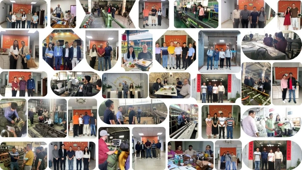
Hydraulic drawbench engineering since 1998
FangRong has been engaged in cold drawing equipment manufacturing since 1998. Its engineering experience covers hydraulic drawbenches, die design, drawing-force calculation, reduction schedules and process automation for non-ferrous and other metal products.
Two manufacturing facilities
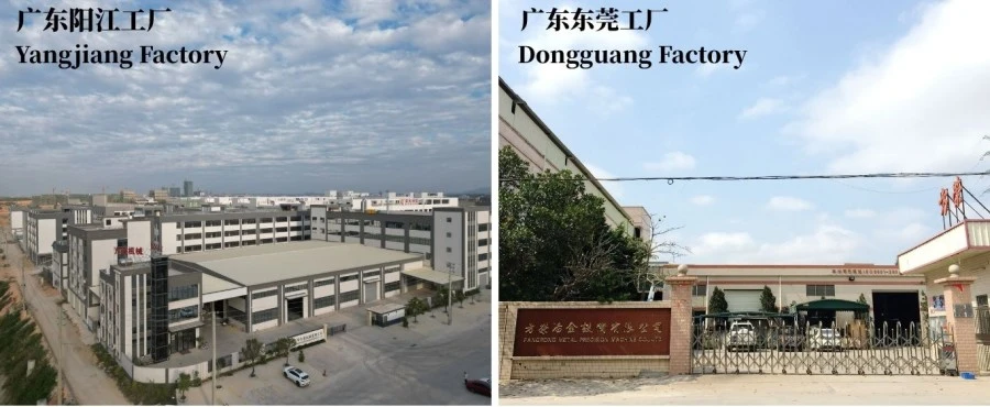
FangRong operates manufacturing facilities in Dongguan and Yangjiang. The two-site production arrangement provides additional manufacturing capacity for standard and customized drawing equipment.
International installations
FangRong equipment has been supplied to customers in more than 70 countries and used across copper, aluminum, steel, stainless steel and other metal-processing applications.
Process-specific engineering
For a busbar project, the important engineering work is not limited to selecting the hydraulic cylinder. FangRong can assist with drawing-force calculations, die configuration, reduction schedules, hydraulic parameters, layout drawings and optional automation based on the customer's actual busbar dimensions.
Factory acceptance testing
Before shipment, machines can undergo idle operation followed by rated-load testing. Where customer samples are available, actual material can be used to check drawing operation, hydraulic stability, machine movement and finished-product requirements before delivery.
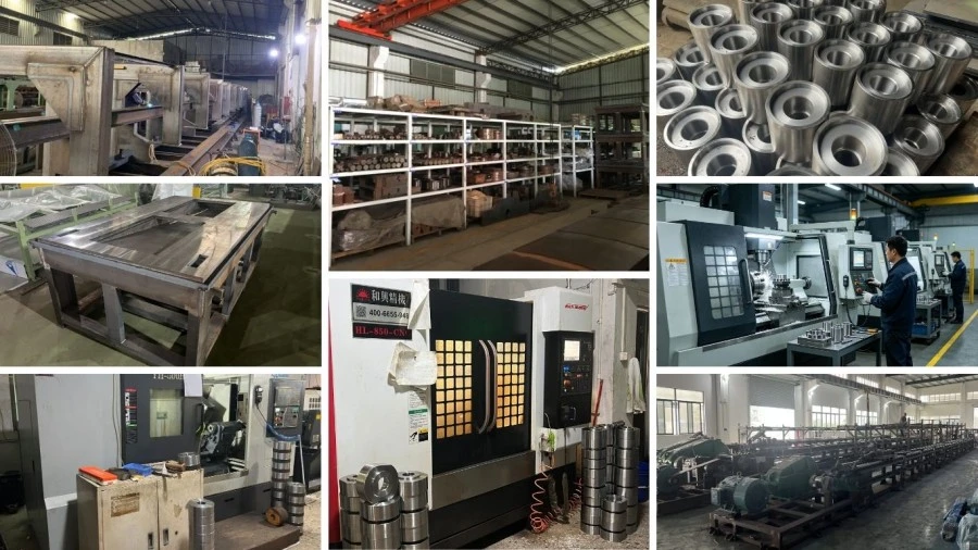
1. Order engineering — Busbar dimensions, material, drawing force, die configuration, hydraulic parameters and automation requirements are reviewed before production.
2. Component inspection — Key components including cylinder tubes, piston rods, seals and structural steel are inspected before assembly.
3. Precision machining — Cylinder bores, piston rods and guide components are machined and finished according to the required dimensional tolerances.
4. Hydraulic assembly — Hydraulic power units, valves, piping and control components are assembled and checked for pressure stability and leakage.
5. Mechanical alignment — The main cylinder, draw carriage and guide system are assembled and aligned to maintain stable movement during drawing.
6. Electrical and PLC integration — The control system is programmed according to the machine configuration and required drawing cycle.
7. Load testing — Machine operation is checked under defined load conditions, with customer material testing where samples are provided.
8. Final inspection — Hydraulic pressure, movement, electrical functions, safety devices, dimensions and general machine condition are inspected before shipment.
9. Export packaging — Components are protected against moisture, corrosion and transportation damage before loading.
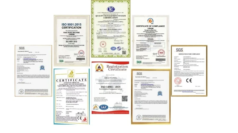
ISO 9001:2015 — Quality management system covering relevant design, manufacturing, installation and service activities. Certificate No. UQ231211R1.
CE — Standard machine configurations can be supplied with CE conformity documentation for applicable machinery safety requirements. The exact declaration and safety configuration should be confirmed for the machine ordered and destination market.
SGS inspection — Third-party inspection can be arranged for customers requiring independent verification before shipment.
Patents — FangRong reports 32 invention patents and more than 100 utility model patents, including patents related to drawing equipment components and tooling systems.
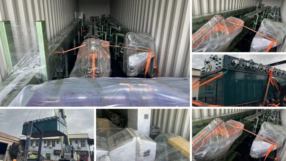
The machine is prepared for export transportation with corrosion protection, moisture protection and suitable wooden packaging for major components. Large hydraulic and mechanical assemblies may be shipped separately according to container loading and site installation requirements.
For quotation, the final shipping method, packing configuration, departure port and Incoterm should be confirmed according to the destination, machine dimensions and order configuration.
The standard application is copper and aluminum busbars. Copper alloys, aluminum alloys and other non-ferrous materials may also be considered when the material condition, drawing force and tooling are suitable. The material grade should be provided before model selection.
The stated model range covers widths from 15 to 400 mm and thicknesses from 2 to 30 mm, with the exact range depending on the model. FR-100T covers 30-400 mm width and 3-30 mm thickness.
There is no single reduction value that applies to every copper or aluminum busbar. The practical reduction depends on material grade and condition, starting and final section, die geometry, lubrication and required mechanical properties. For larger total reductions, multiple drawing passes and intermediate annealing may be required.
Yes. Cold deformation generally increases hardness and strength through work hardening. The degree of change depends on the reduction and starting material condition. If a specific tensile strength, hardness or elongation is required, the drawing schedule should be designed around the target mechanical properties.
Drawing can significantly improve surface condition, but the final result also depends on the incoming surface, die quality, die geometry and lubrication. A drawing machine cannot remove deep defects that already exist below the original surface.
Compare the required drawing force rather than choosing only by finished busbar width. Provide the starting and target dimensions, material grade and reduction schedule. FangRong can calculate the estimated drawing force and recommend the appropriate model.
No. The 2-12 m/min range is an adjustable operating range, not a mandatory production speed. The suitable setting depends on section geometry, reduction, material, lubrication, die condition and required surface quality. Higher speed is useful only when the complete process can maintain stable drawing conditions.
Yes. An optional straightening unit can be integrated when the finished busbar requires additional control of bow or twist. Feeding and other downstream handling equipment can also be considered according to the production layout.
The standard machine configuration includes the hydraulic drawing system, main cylinder, draw carriage, die holder, hydraulic power unit and PLC/HMI control system. Tooling for a specific busbar size should be confirmed separately because die dimensions depend on the customer's starting and finished sections.
Provide the material grade, starting width and thickness, finished width and thickness, required drawing length, number of passes, target output and available factory power supply. A drawing or cross-sectional diagram is also useful for non-standard profiles.
The FR-series uses an effective drawing length of 6-12 meters. Longer or application-specific drawing lengths can be evaluated during engineering design.
Standard models generally require approximately 30-60 days, while larger or customized machines may require 60-90 days. The confirmed lead time should be stated in the quotation because tooling, automation, machine size and factory workload can affect production time. Expedited delivery should be confirmed case by case rather than assumed.
The standard commercial arrangement is 30% deposit upon order confirmation and 70% before shipment after factory acceptance testing. Alternative terms can be discussed for specific projects.
The standard warranty period is 12 months from commissioning. Warranty coverage and exclusions should be confirmed in the final sales contract.
Yes. FangRong provides installation supervision, commissioning support and operator training. On-site training normally covers machine operation, die changing, routine maintenance and basic fault diagnosis. Foundation drawings and anchor-bolt layouts can be supplied before installation.
Yes. Where practical, customer samples can be used for factory testing. This is particularly useful when the busbar section is large, non-standard, or when the customer has specific dimensional, surface or mechanical-property requirements.
CE documentation can be supplied for applicable standard machine configurations. Because machinery conformity depends on the actual machine configuration and destination market, the applicable declaration, safety devices and documentation should be confirmed before order.
Yes. Provide the copper or aluminum grade, starting section, target section and required process. FangRong can use these parameters to evaluate the drawing force, select the appropriate FR-series model and recommend a suitable reduction and tooling configuration.
Address
NO.163,Shatong Road,Shabu 2nd Industrial Zone, Dalang Town, Dongguan City, Guangdong, China