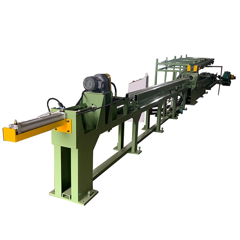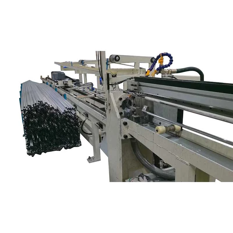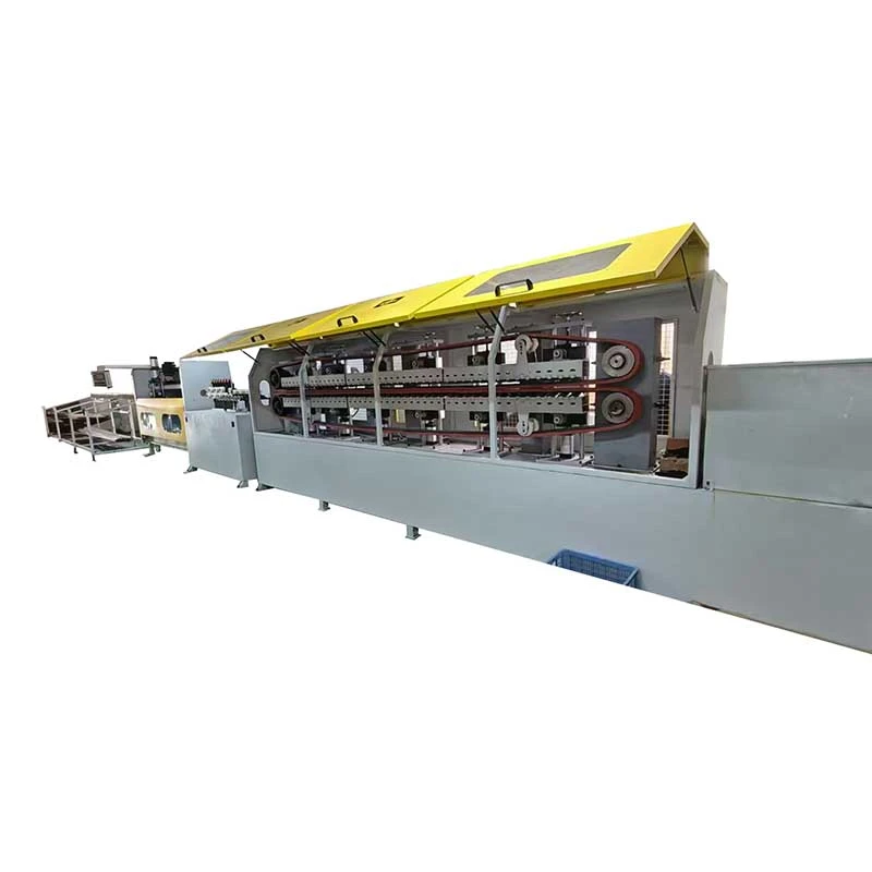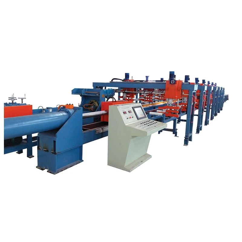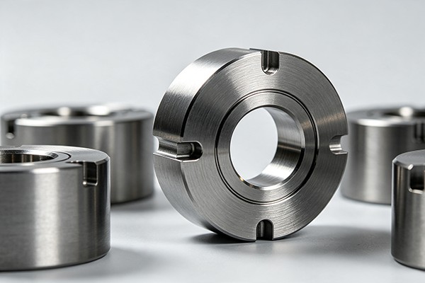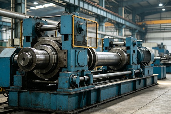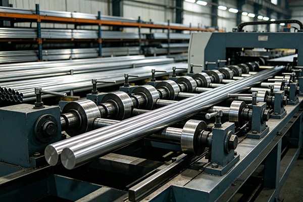

We offer a comprehensive range of precision metal processing equipment, including straightening, cold drawing, pointing, chamfering, cutting, thread rolling machines, and drawing dies, tailored for tube, bar, and wire materials across diverse industries.
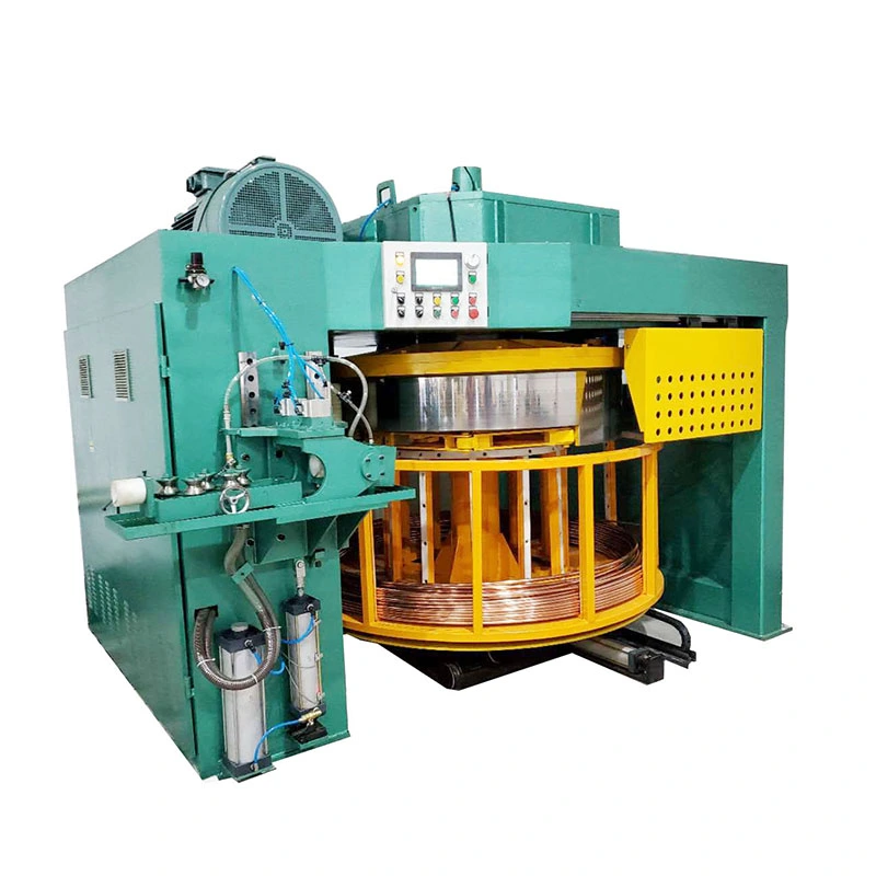
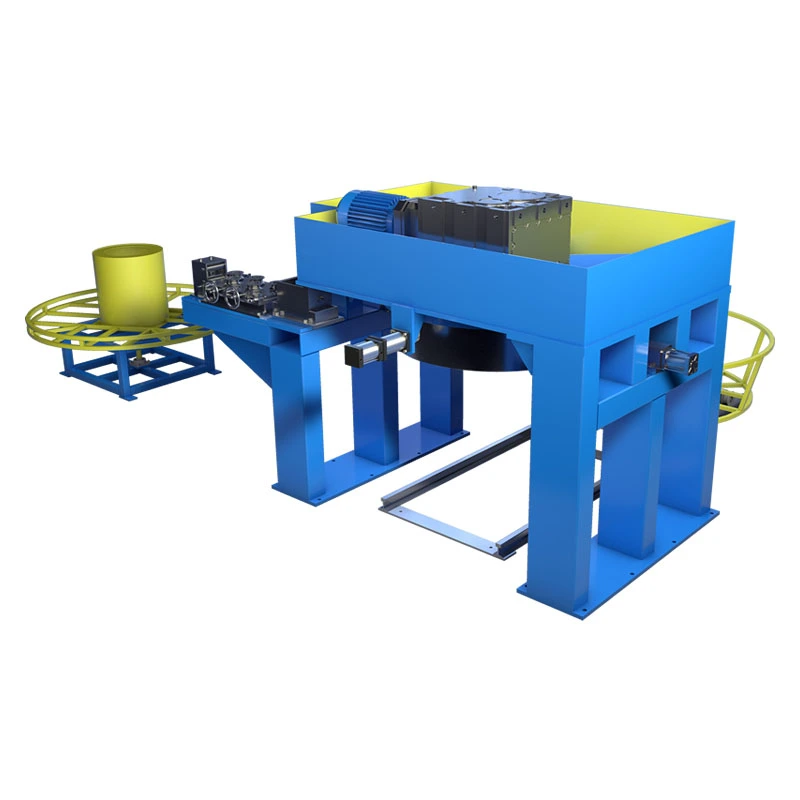
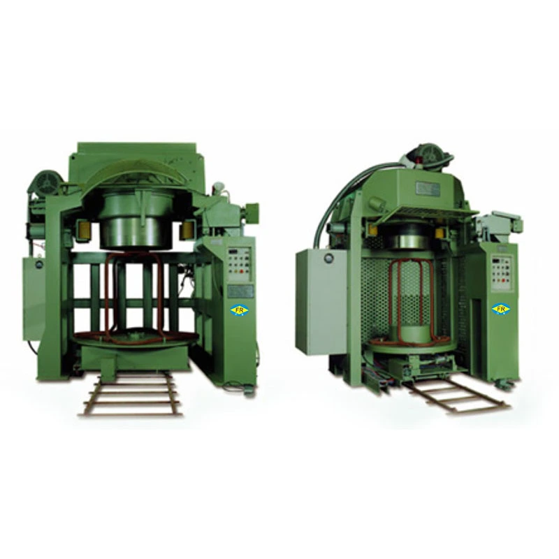
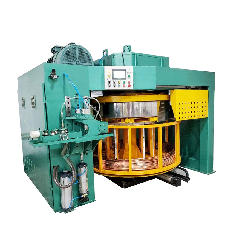
The Inverted Coil Drawing Machine combines continuous drawing and coiling for copper, aluminum, stainless steel, and carbon steel tubes or wires. With drawing speeds up to 400 m/min and tube diameters of 3–25 mm, it reduces cutting, handling, and intermediate storage. Coil drums range from 250–2200 mm. Frequency-controlled speed regulation maintains stable drawing tension and surface quality. Suitable for HVAC, refrigeration, electrical, automotive, and medical tubing production.
The Inverted Coil Drawing Machine is designed for continuous drawing of metal tubes and wires where the finished material needs to leave the drawing line in coil form. Unlike a conventional drawbench that works with fixed-length material, the inverted configuration combines drawing, take-up and coil handling in one production line, making it suitable for long-length products in copper, aluminum, stainless steel, carbon steel and alloy materials.
The FR-D series uses an overhead drive and downward-facing coil arrangement. This layout leaves the coil receiving area accessible from below and is particularly useful where production requires frequent coil changes, long continuous lengths or high line speeds. Depending on the model and material, the series covers diameters from 3 mm to 25 mm, with drum diameters from 250 mm to 2200 mm and maximum listed speeds up to 400 m/min.
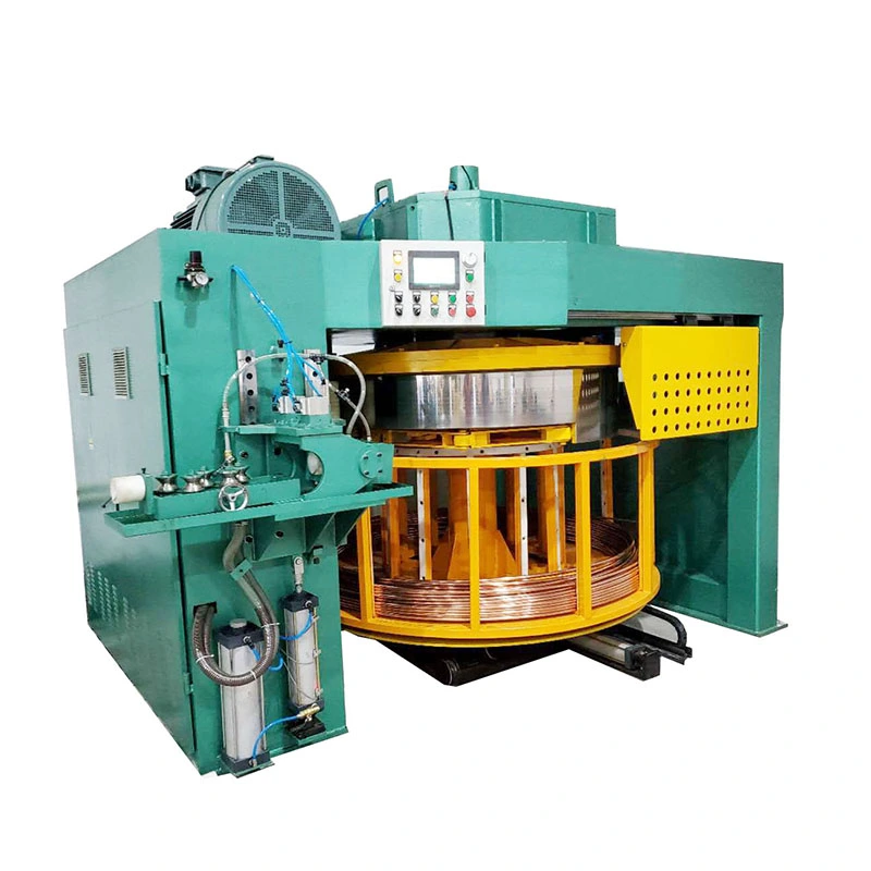
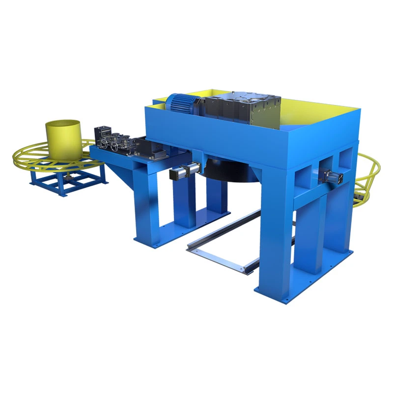
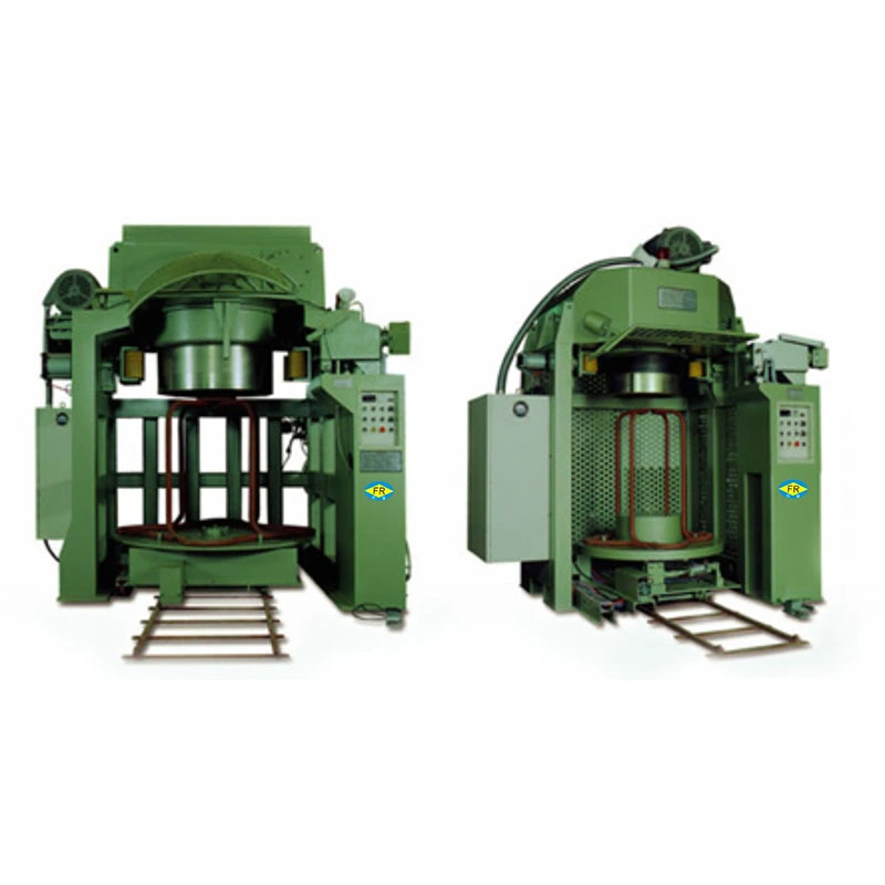
The main reason to use an inverted drawing line is not simply the machine orientation. It is the need to produce long continuous lengths without repeatedly cutting the material into straight pieces. This can reduce intermediate handling when the downstream process also uses coil-fed material.
The configuration is especially relevant for:
Copper and aluminum tubes where high line speed and continuous coiling are important for HVAC, refrigeration and heat-exchanger production.
Small-diameter stainless steel tubes where controlled drawing and coil delivery are required for medical, instrumentation or fluid-control components.
Steel and alloy wires used as continuous feedstock for fasteners, cold heading and other downstream forming operations.
The machine should be evaluated as part of the complete production route. Die reduction, lubrication, incoming material condition, required final dimensions and downstream coil requirements all affect the practical machine configuration.
Specify the final outside diameter, wall thickness where applicable, material grade and required coil weight before choosing a model. A Inverted Coil Drawing Machine selected only according to maximum diameter may be unnecessarily large if most production runs are at smaller sizes.
The starting tube or wire diameter determines the drawing reduction and required drawing load. For tube applications, wall thickness and internal tooling also need to be considered. If several sizes are produced on the same line, provide the complete size range rather than only the largest product.
Drum diameter affects the bending condition of the drawn product and the available coil capacity. Larger drums are generally more suitable for products that cannot tolerate a small bending radius or for applications requiring heavier coils. The correct size should be determined together with tube diameter, material properties and target coil weight.
The maximum speed in the specification table is a machine capability, not a guaranteed production speed for every material. Copper and aluminum can normally be processed at substantially higher speeds than stainless steel. Lubrication, die geometry, reduction per pass, cooling and required surface quality also limit practical speed.
The required coil diameter, coil weight and coil dimensions should be confirmed before ordering. If the finished coil is transferred directly to a cutting, annealing, cleaning or packaging line, the take-up arrangement should be matched to that handling method.
Automatic cutting, clamping, lubrication, length counting, coil-change sequencing and hydraulic or pneumatic functions can be integrated into the line. These requirements should be specified during engineering rather than added after the machine is completed.
| Production requirement | Main selection factor |
| Small copper or aluminum tube | Diameter range, drawing speed and cooling |
| Long continuous tube | Drawing stability, die reduction and take-up arrangement |
| Stainless steel tube or wire | Drawing load, lubrication, die configuration and practical speed |
| Heavy finished coil | Drum diameter, take-up motor and coil handling capacity |
| Multiple product sizes | Usable diameter range and tooling change requirements |
| Automatic downstream production | PLC functions, length counting and coil-change interface |
The FR-D range includes eight models. The figures below are the standard model configuration; actual production speed and suitable diameter depend on material, reduction, tooling and process requirements.
| Model | Motor Power (kW) | Gearbox | Diameter Range (mm) | Max Speed (m/min) | Drum Diameter (mm) | Take-up Motor (kW) | Take-up Gearbox |
| FR-D250 | 5.5 / 7.5 | WPX120 | ≤3 | 80 | 250 | 1.1 | WPO60 |
| FR-D600 | 11 / 15 | KAF87/97 | 3-6 | 150 | 600 | 1.5 | WPO80 |
| FR-D800 | 18.5 / 22 | KAF97 | 3-8 | 150 | 800 | 1.5 | WPO80 |
| FR-D1000 | 22 / 37 | KAF107 | 3-10 | 200 | 1000 | 2.2 | WPO100 |
| FR-D1200 | 37 / 45 | KAF107/127 | 3-12 | 200 | 1200 | 2.2 | WPO100 |
| FR-D1500 | 45 / 55 | KAF127 | 3-15 | 250 | 1500 | 3 | WPO120 |
| FR-D1800 | 55 / 75 | KAF127/157 | ≤20 | 300 | 1800 | 3 / 5.5 | WPO155 |
| FR-D2200 | 90 / 110 | KAF167 | ≤25 | 400 | 2200 | 5.5 / 7.5 | WPO250 |
Important: the listed maximum speeds are reference machine ratings and should not be treated as the recommended operating speed for stainless steel or other high-strength materials. Final speed is established from the material, starting size, reduction schedule, die design, lubrication and required surface quality.
An adjustable cross-roller straightening section can be installed before the drawing die to correct incoming tube or wire alignment. This is useful when the incoming coil has significant curvature or when consistent die entry is important.
For high-speed production, heat generated by drawing and friction must be considered together with lubricant condition and die temperature. Forced-air cooling can be included where the process requires additional heat management.
The take-up unit is not only a winding device. Coil diameter, winding speed and product guidance affect how tightly and consistently the finished material is arranged. The take-up specification should therefore be matched to the finished coil weight and the handling equipment used after drawing.
Die material, approach geometry and lubrication are selected according to the workpiece material and reduction. Copper, aluminum and stainless steel should not automatically use the same tooling or lubrication parameters.
Used for continuous drawing of tubes for air-conditioning, refrigeration, heat exchangers, electrical components and other coil-fed applications. These materials are suitable for higher-speed production when the reduction and lubrication system are properly matched.
Used for small-diameter precision tubing, instrumentation, medical components and fluid-control products. Compared with copper and aluminum, stainless steel generally requires lower drawing speeds and closer control of lubrication, die wear and reduction.
The continuous coil format is suitable for wire that feeds directly into subsequent forming operations such as cold heading and fastener production. The required drawing route depends on the steel grade, starting wire condition and final diameter.
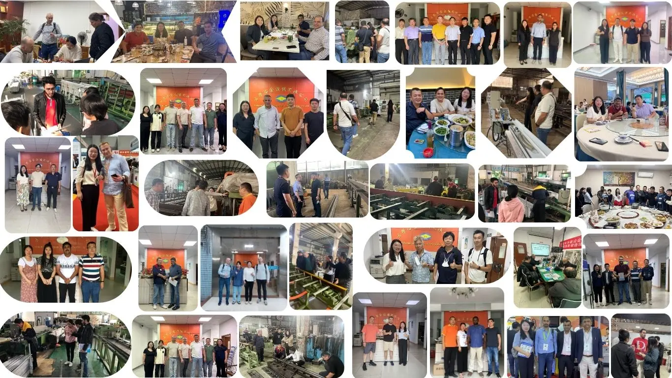
FangRong has manufactured drawing equipment since 1998 and operates production facilities in Dongguan and Yangjiang. The manufacturing scope includes cold drawing machines, straightening equipment and related metal forming machinery.
For an inverted drawing line, factory inspection focuses on the parts that directly influence continuous running: drum runout, drive operation, gearbox condition, electrical control, take-up movement, safety functions and the quality of the finished coil.
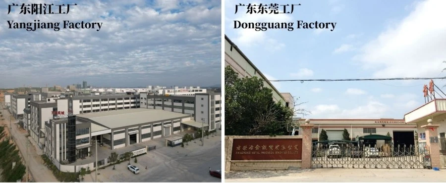
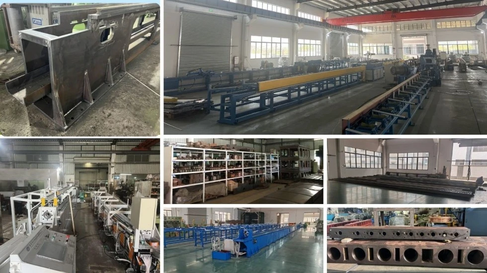
Engineering: confirm material, dimensions, reduction, speed, drum size, take-up requirements and automation.
Machining: manufacture the frame, drum, shafts, transmission parts and other critical components according to engineering drawings.
Assembly: integrate the drawing drive, drum, die box, straightening section, take-up and control system.
Control commissioning: test speed regulation, length counting, operating logic, safety circuits and optional automatic functions.
Factory testing: inspect mechanical movement, electrical operation, drum runout, coil formation and machine response under the agreed test conditions.
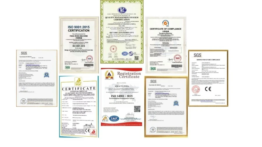
ISO 9001:2015: Quality management system covering design, manufacturing and related service activities. Certificate No. UQ231211R1.
CE documentation: Safety-related design and documentation can be provided for machines supplied to applicable markets.
SGS inspection: Third-party inspection can be arranged according to the customer's inspection requirements.
Component selection: Motor, gearbox, pneumatic, electrical, PLC, HMI and inverter brands can be specified according to budget, local service availability and project requirements.
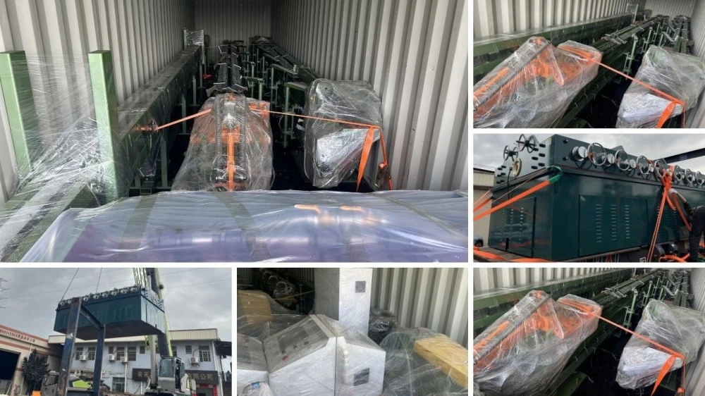
The Inverted Coil Drawing Machine is prepared for export shipment with suitable mechanical protection, moisture protection and corrosion prevention. Large equipment is divided into transportable sections where required, with packing and lifting arrangements considered during the engineering stage.
Typical lead time is 30-60 days for standard smaller models and approximately 60-90 days for larger or customized configurations. The final schedule depends on model, component selection, tooling and automation scope.
Provide the material grade, tube or wire type, starting diameter, final diameter, wall thickness for tubes, required production speed, target coil weight and downstream handling method. If several products will run on the same machine, provide the complete size range.
The drum should be selected according to the product diameter, material's allowable bending condition, required coil diameter and coil weight. A larger drum is not automatically better; it increases equipment size and cost and should be justified by the product and production requirements.
No. Stainless steel normally requires substantially lower drawing speeds because of its higher deformation resistance and different heat and lubrication requirements. The actual speed should be established from the material grade, reduction and die configuration rather than from the copper-rated maximum.
Yes, provided the sizes fall within the usable range of the selected model and suitable dies and process parameters are available. For a wide product range, the die-changing method, lubrication arrangement and speed-control range should be considered during machine selection.
The take-up system controls the receiving coil rather than the primary drawing load. Its capacity and speed must match the finished product, coil diameter and required winding condition. An undersized take-up system can become a limitation even when the main drawing drive has sufficient power.
For a complete production test, check drawing speed, dimensional consistency, drum operation, take-up synchronization, coil formation, electrical and safety functions, lubrication and cooling systems. When possible, testing with the customer's actual tube or wire provides a more useful acceptance reference than an unloaded machine test alone.
Address
NO.163,Shatong Road,Shabu 2nd Industrial Zone, Dalang Town, Dongguan City, Guangdong, China