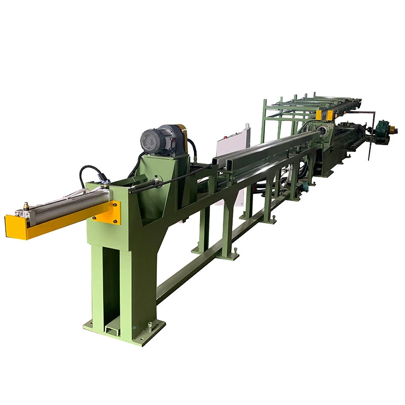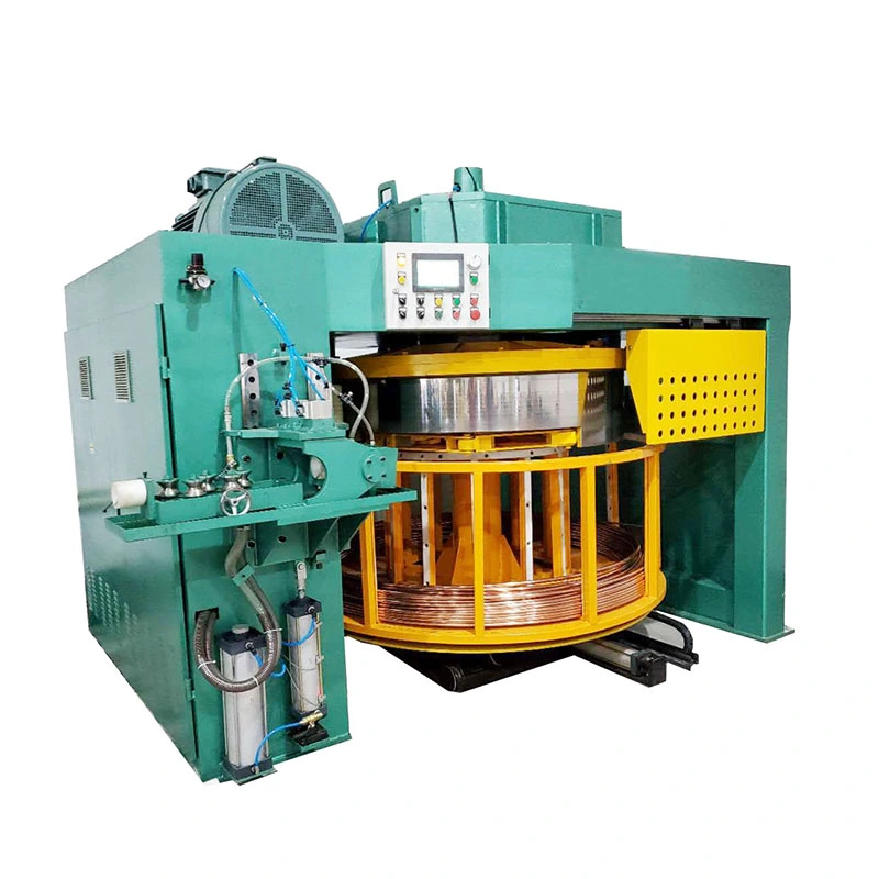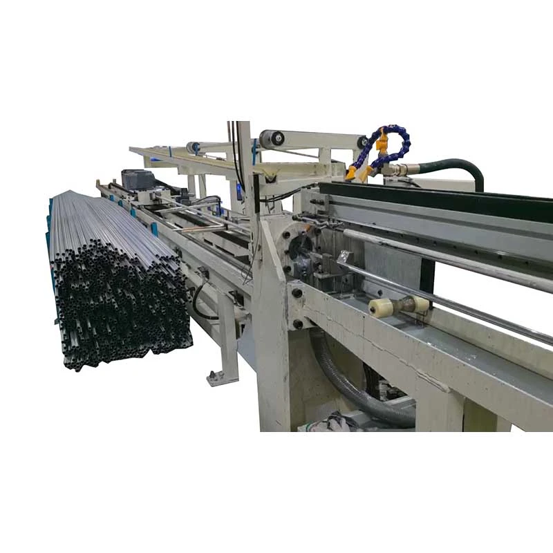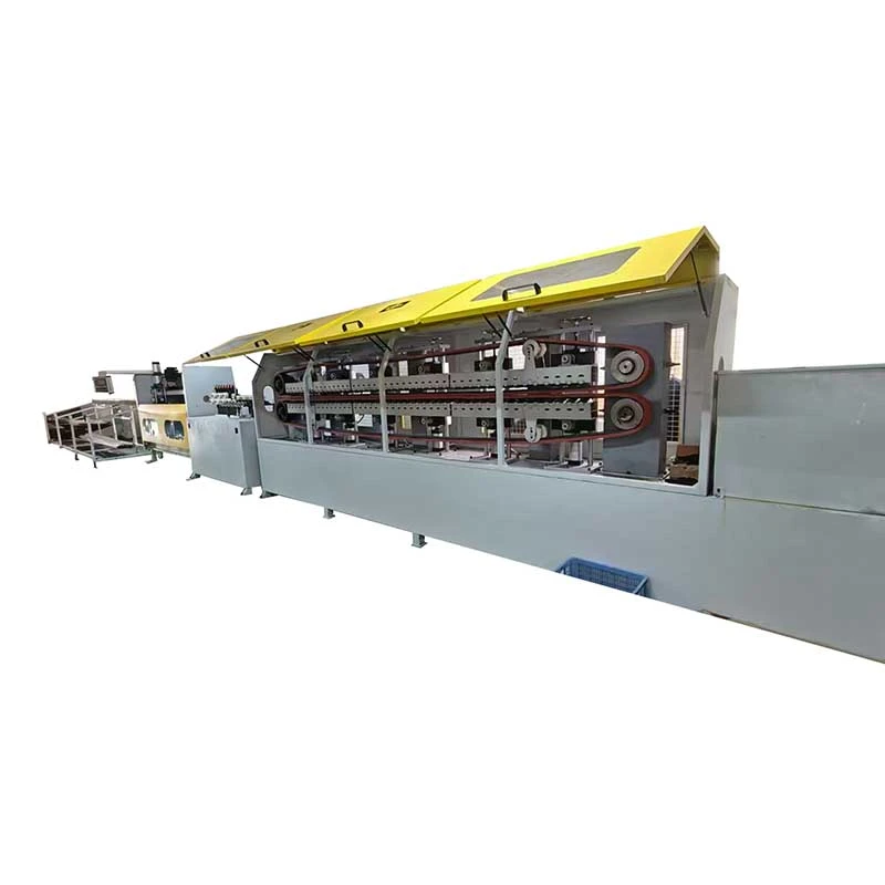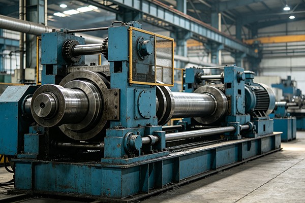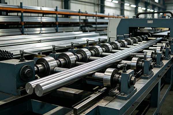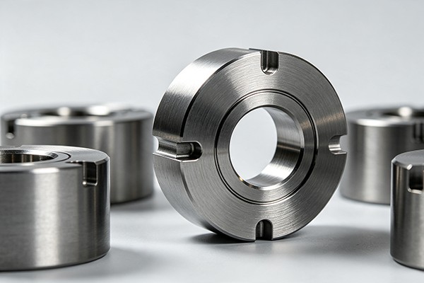

We offer a comprehensive range of precision metal processing equipment, including straightening, cold drawing, pointing, chamfering, cutting, thread rolling machines, and drawing dies, tailored for tube, bar, and wire materials across diverse industries.
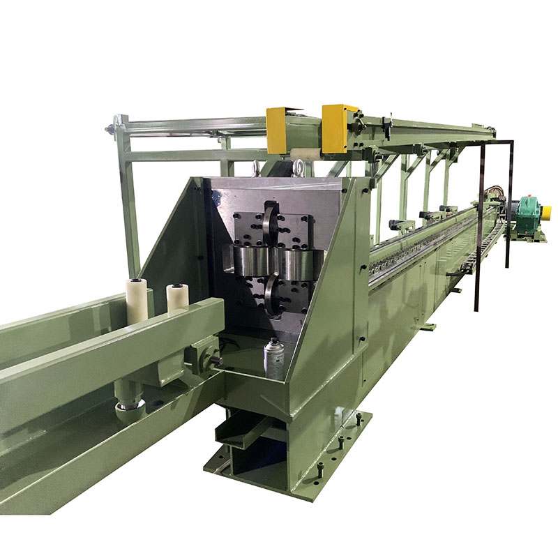
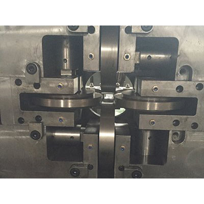
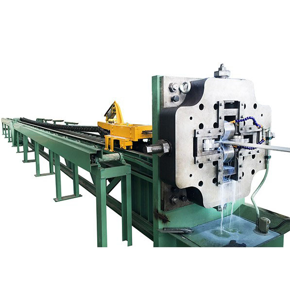
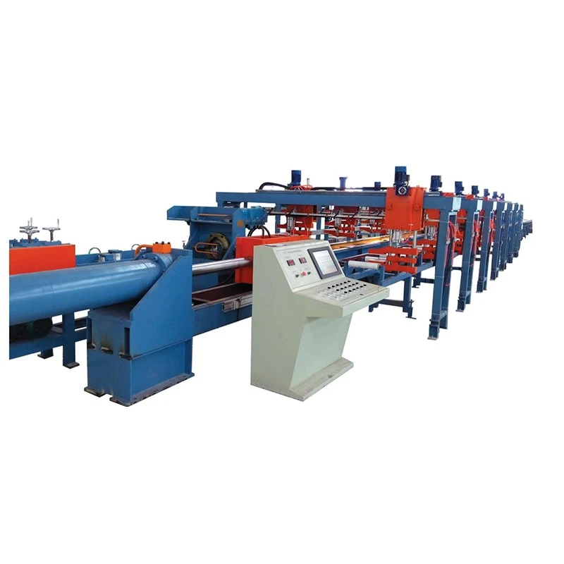
The Four Rollers Rolling Drawing Machine is designed for cold drawing guide rails, sliders, and special-shaped steel sections. With drawing forces of 300–750 kN and speeds up to 13 m/min, it processes S55C, 20CrMo, and similar steels with tensile strength up to 900 MPa. The dual-chain drive, pneumatic clamping carriage, adjustable die holder, and rigid C-frame ensure stable drawing and straightness of ≤1 mm/m. PLC touchscreen control supports precise speed adjustment. Suitable for construction machinery, automation equipment, and precision steel sections.
The Four Rollers Rolling Drawing Machine is a chain-driven cold drawbench designed for the precision drawing of special-shaped steel sections, including guide rails, sliders, asymmetric profiles, and other non-round sections. The workpiece is pre-pointed at the leading end and pulled through a precision drawing die or rolling die, reducing the cross-sectional area while controlling the finished profile, dimensions, and straightness.
Unlike a conventional bar drawing machine used mainly for round products, this machine is configured for profiles where die alignment, pulling stability, and finished straightness are critical. The spherical die holder allows the die angle to be adjusted during setup, providing an additional means of correcting the straightness of the drawn section.
The standard range includes FR-30, FR-45, and FR-65 models with rated drawing forces of 300 kN, 450 kN, and 650 kN respectively. The FR-65 uses a dual-chain drive for higher-load applications, while the FR-30 and FR-45 use single-chain configurations.
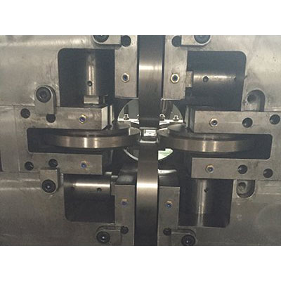
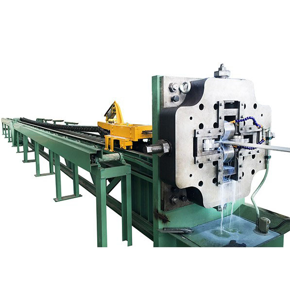
The machine combines controlled pulling force, precision die guidance, and automated material handling in one drawing cycle.
1. Material loading — Steel bars or special-shaped sections such as S55C and 20CrMo are loaded onto the stacking table, normally with an overhead crane. The workpiece is then transferred to the feed roller table and positioned for drawing.
2. Workpiece preparation and die entry — The leading end of the workpiece is pre-pointed so it can pass through the die opening. The die is installed in a spherical die sleeve. Its tapered bore, typically around 6°, allows the die holder to be adjusted to control the drawing direction.
3. Drawing — The carriage grips the pointed end using a wedge-type pneumatic clamping mechanism. The main drive, consisting of a DC motor, gearbox, and heavy-duty chain system, pulls the carriage along precision-machined guide rails.
4. Controlled unloading — After the drawing stroke is completed, the carriage jaws release the workpiece. The finished section is transferred onto the receiving device fitted with nylon rollers to reduce contact damage. A lateral transfer mechanism then moves the product away from the drawing line.
5. Carriage return — The drawing carriage returns to its starting position, allowing the next workpiece to enter the production cycle.
Loose dimensions after hot processing — Hot-rolled and extruded sections can have dimensional variation that makes them unsuitable for precision assembly. Cold drawing reduces the cross-section through a controlled die opening and provides more consistent finished dimensions.
Straightness variation — Long guide rails and asymmetric profiles are sensitive to bending during previous manufacturing and handling operations. The adjustable spherical die holder allows operators to compensate for drawing-direction deviations during setup.
Surface condition after hot forming — Drawing can improve the surface condition of a properly prepared workpiece by bringing the material into controlled contact with the die. However, cold drawing does not automatically remove all surface defects, so severe scale, pits, seams, or cracks should be addressed before drawing.
High pulling loads on long profiles — Special-shaped steel sections can require substantial drawing force, particularly when working with higher-strength alloys or larger reductions. The FR series provides different force capacities, with the FR-65 using a dual-chain drive for heavy-duty applications.
Handling damage after drawing — Long precision sections can be scratched or dented during unloading if they fall directly onto metal surfaces. Nylon rollers and the lateral transfer system are used to reduce impact and surface contact during product handling.
The FR-30, FR-45, and FR-65 cover different drawing-force requirements. Model selection should be based on material strength, starting and finished cross-sections, reduction per pass, and required production output rather than tonnage alone.
The FR-65 uses two heavy-duty chain lines to distribute the pulling load more evenly across the carriage. Its main chain uses a 200 mm pitch straight-plate construction. This configuration is intended for applications where the drawing force is high and stable load transmission is important.
The die holder uses a spherical sleeve arrangement that permits angular adjustment of the die. This allows operators to fine-tune the drawing direction and finished straightness without repeatedly removing and reinstalling the die.
The carriage uses a wedge-type pneumatic clamping mechanism to grip the pointed end of the workpiece. After the drawing stroke, the jaws release automatically for unloading and carriage return.
The C-type frame is welded from structural steel and stress-relieved before machining. Guide surfaces, mounting faces, and relevant base planes are machined to establish the alignment required for carriage movement and die positioning.
The drawing carriage is driven by a DC motor and heavy-duty gearbox. Depending on the model, Parker or Siemens DC drives are used. Variable-speed control allows the drawing speed to be adjusted according to the workpiece and process requirements.
After drawing, the workpiece is transferred to a receiving device equipped with nylon rollers. A chain-type lateral transfer mechanism then moves the finished section away from the machine, reducing manual handling between drawing cycles.
The machine base incorporates sealed welded plates that can collect drawing lubricant and prevent it from spreading directly onto the workshop floor. The arrangement also simplifies cleaning around the drawing line.
The electrical system uses PLC-based control with an HMI touchscreen for machine operation, parameter setting, monitoring, and safety-related signals. Manual and automatic operating modes can be configured according to the production process.
The die holder can accommodate tungsten carbide dies and rolling dies, allowing the tooling configuration to be matched to the workpiece material, profile geometry, and reduction requirements.
Choose the drawing machine according to the actual drawing force rather than simply the nominal section size. The required force is affected by material grade, tensile strength, starting and finished dimensions, reduction per pass, friction, lubrication, and die geometry.
For continuous production, it is generally preferable to avoid operating continuously at the absolute maximum force. The actual allowable working load should be confirmed through force calculation and the machine manufacturer's engineering assessment.
| Parameter | FR-65 | FR-30 | FR-45 |
| Configuration | Dual-chain, single-line | Single-chain, single-line | Single-chain, single-line |
| Rated Drawing Force | 650 kN (65 t) | 300 kN (30 t) | 450 kN (45 t) |
| Maximum Drawing Force | 750 kN at 0–13 m/min | 350 kN at 0–13 m/min | 550 kN at 0–12 m/min |
| Rated Drawing Speed | Approximately 13 m/min | Approximately 13 m/min | Approximately 12 m/min |
| Speed Range | 0–37 m/min | 0–19 m/min | 0–18 m/min |
| Effective Drawing Length | 12 m | 12 m | 12 m |
| Bed Length | ≤16 m | 25 m overall | 25 m overall |
| Main Motor | Z4-280-41, 166 kW, 675/1900 rpm, DC | 75 kW, 1000/2000 rpm, DC | 110 kW, 1000/2000 rpm, DC |
| Main Gearbox | ZFY560, ratio 112, 185 kW input | ZFY400-112 | ZFY500-160 |
| Main Chain | 200 mm pitch, heavy-duty straight-plate chain | 180 mm pitch, straight chain, 2 × 2 | 240 mm pitch, straight chain, 2 × 2 |
| DC Drive | Siemens 6RA80 | Parker | Parker |
| PLC/HMI | Inovance | Inovance | Inovance |
| Approx. Footprint | 31 m × 4.1 m | 25 m × 1.8 m | 25 m × 2.1 m |
Material: Provide the exact steel grade, heat-treatment condition, tensile strength, and yield strength where available. S55C, 20CrMo, and other alloy steels behave differently during cold deformation.
Starting and finished dimensions: For special-shaped sections, provide drawings showing all critical dimensions rather than only the nominal profile name.
Reduction per pass: The reduction must be evaluated together with material strength and die geometry. A higher reduction generally increases drawing force and may require multiple passes or intermediate heat treatment.
Required straightness: State the straightness requirement together with the measurement method and product length. A claimed straightness value is meaningful only when the inspection method and product condition are defined.
Production speed: The appropriate drawing speed depends on material, die type, lubrication, reduction, and surface requirements. Maximum machine speed should not automatically be treated as the recommended production speed.
Die type: Specify whether the process uses a tungsten carbide die, rolling die, or another tooling arrangement. The die type affects both drawing force and surface condition.
The machine is suitable for drawing steel guide rails, sliders, and other linear-motion sections where finished straightness and dimensional consistency are important.
For guide rail production, the die profile must be designed around the actual cross-section. Critical dimensions such as rail width, height, groove geometry, corner radius, and reference surfaces should be included in the die drawing.
The Four Rollers Rolling Drawing Machine can be configured for non-round steel sections, including asymmetric profiles, T-sections, channel-type profiles, angle sections, and customer-specific shapes where cold drawing is suitable.
Cold-drawn profiles can be used for selected structural, chassis, suspension, and mechanical components where controlled dimensions and straightness are required. The suitability of the process depends on the steel grade and required reduction.
Applications include special profiles used in construction equipment, guide systems, structural assemblies, and other machinery components where long sections need controlled dimensions after hot rolling or extrusion.
The machine can also be used for precision bar stock and customized industrial profiles when the required cross-section and material properties fall within the machine's drawing-force range.
S55C Guide Rails: The FR-65 can be configured for heavy-duty guide rail drawing where the required drawing force calls for a dual-chain drive. The spherical die holder provides an adjustment point for controlling finished straightness during setup.
20CrMo Slider Profiles: The FR-45 can be considered for higher-strength alloy steel profiles when the calculated drawing force remains within the machine's capacity. Actual reduction and surface results should be verified according to the customer's material condition, die design, and lubrication system.
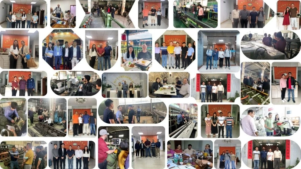
FangRong began its cold drawing equipment business in 1998 through a joint venture with a Taiwanese drawing equipment specialist and became wholly owned in 2013. The company has continued to focus on cold drawing, straightening, and related metal forming equipment.
Dongguan Fangrong Metallurgical Equipment Co., Ltd. and Yangjiang Fangrong Machinery Co., Ltd. support equipment manufacturing and assembly. Combined annual production capacity is more than 650 machines.
FangRong equipment has been exported to more than 70 countries and has been used by customers working with steel, stainless steel, copper, brass, aluminum, and specialty alloys.
For a complete drawing project, machine selection is only one part of the engineering work. FangRong can support die selection, foundation planning, installation supervision, commissioning, operator training, spare parts supply, and remote troubleshooting.
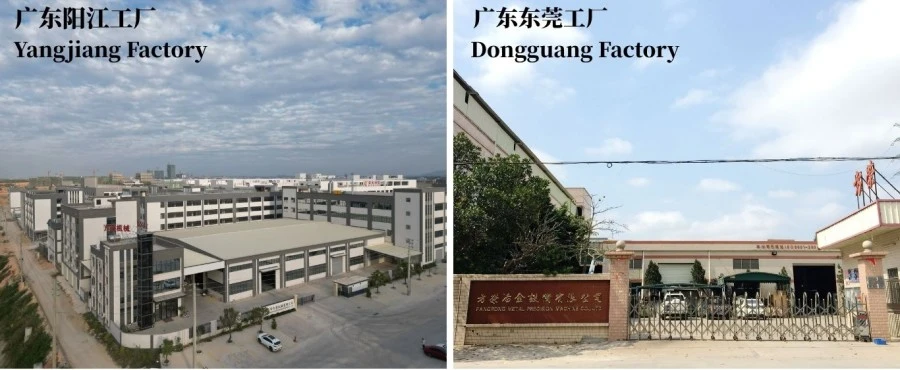
Dongguan Fangrong Metallurgical Equipment Co., Ltd. — Located in Dalang Town, Dongguan City, the facility focuses on cold drawing machines, straightening equipment, thread rolling machines, and related metal forming equipment.
Yangjiang Fangrong Machinery Co., Ltd. — Located in Yangdong District, Yangjiang City, the second facility expands manufacturing capacity and supports larger equipment projects.
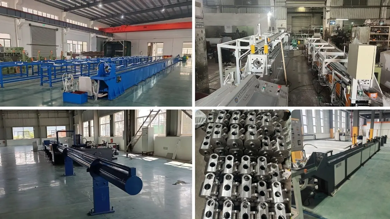
1. Material inspection — Structural steel plates and sections are checked before fabrication.
2. Cutting and forming — Frame and structural components are cut and prepared according to engineering drawings.
3. Frame welding — The C-type frame and base are welded and inspected before stress relief.
4. Stress relief — Post-weld stress relief is performed to reduce residual welding stress before precision machining.
5. Integral machining — Guide surfaces, mounting faces, and critical base planes are machined to establish the required alignment.
6. Mechanical assembly — The gearbox, chain system, carriage, die holder, and receiving mechanisms are assembled.
7. Electrical and pneumatic integration — Motors, drives, PLC, HMI, sensors, and pneumatic components are connected and tested.
8. PLC programming — Control logic, operating sequences, monitoring functions, and safety-related signals are configured.
9. Machine testing — Machine movement, drawing system, carriage operation, unloading, transfer, and control functions are checked.
10. Final inspection — Mechanical alignment, electrical safety, control functions, and relevant machine performance are inspected before shipment.
11. Export packaging — The machine is protected against corrosion, impact, and transportation damage before loading.
Before shipment, the machine can be checked through no-load operation and drawing tests according to the agreed technical specification. Where the customer provides actual workpiece samples, production testing can be used to verify drawing force, carriage movement, speed, die installation, unloading, and finished-product requirements.
For applications with strict straightness or dimensional requirements, the acceptance criteria should be defined in advance, including the material condition, product length, tolerance, measurement method, and test quantity.
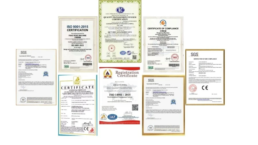
ISO 9001:2015 — Quality management system covering relevant design, manufacturing, installation, and service activities. Certificate No. UQ231211R1.
CE Marking — Applicable standard FR-series equipment is supplied with CE documentation for the relevant machinery safety requirements.
SGS Inspection — Independent inspection services can be arranged according to project requirements.
National Patents — FangRong holds 32 invention patents and more than 100 utility model patents covering equipment structures and related technologies.
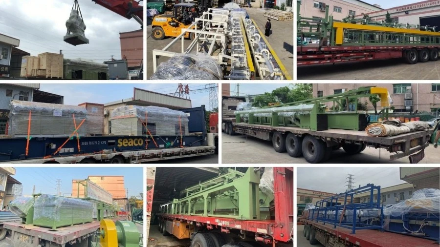
The Four Rollers Rolling Drawing Machine is prepared for long-distance transportation with structural protection, corrosion prevention, and component-specific packaging. Large machine sections can be shipped according to the final equipment configuration and site logistics requirements.
Before shipment, foundation drawings, anchor bolt layouts, equipment documentation, electrical information, and other installation-related documents can be provided according to the project scope.
The machine is mainly used for cold drawing special-shaped steel sections such as guide rails, sliders, rails, and other profiles with non-round cross-sections. The actual suitability depends on the profile geometry, material grade, incoming dimensions, required reduction, and drawing force. A sample profile or detailed section drawing should be provided for machine and die selection.
Model selection should be based on the calculated drawing force rather than profile size alone. The FR-30, FR-45, and FR-65 provide rated drawing forces of 300 kN, 450 kN, and 650 kN respectively, with higher maximum force capacities. Material strength, cross-section reduction, die friction, drawing speed, and production requirements should all be considered when determining the appropriate model.
The spherical die holder allows the die position and angle to be adjusted to the actual drawing direction. This is particularly useful for asymmetric profiles, where small alignment errors can create uneven loading, dimensional deviation, or surface marks. Proper die alignment also helps maintain stable drawing conditions over longer production runs.
Drawing can improve dimensional consistency and straightness, but the final result is not determined by the drawbench alone. Incoming material straightness, profile accuracy, residual stress, die geometry, reduction per pass, machine alignment, and drawing parameters all affect the result. For tight straightness requirements, the target should be verified through sample drawing and measurement before finalizing the machine configuration.
Yes, provided the profiles fall within the machine's force, working length, carriage, and die-size limits. Different profiles normally require dedicated drawing dies or tooling, while the same drawbench can be used for multiple products. For frequent product changes, die-holder accessibility and tooling changeover time should also be considered during machine selection.
The most useful information includes the material grade, incoming profile dimensions, finished dimensions, profile drawing or CAD section, starting and finished length, required reduction, target straightness and surface condition, production quantity, and preferred drawing speed. These parameters allow the required drawing force, die configuration, machine model, and auxiliary handling system to be evaluated before quotation.
Address
NO.163,Shatong Road,Shabu 2nd Industrial Zone, Dalang Town, Dongguan City, Guangdong, China