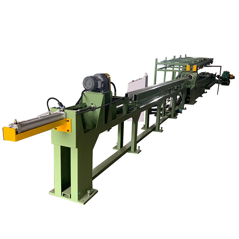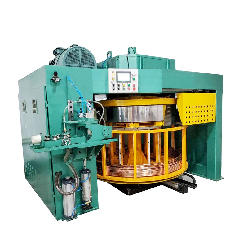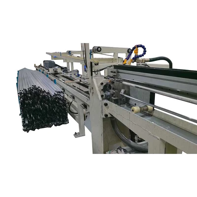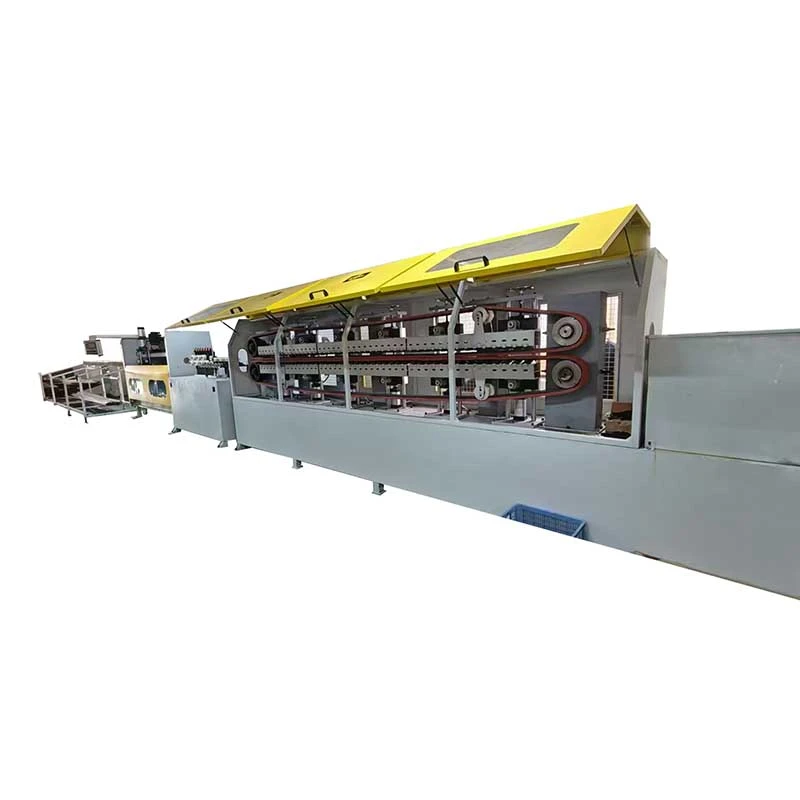

We offer a comprehensive range of precision metal processing equipment, including straightening, cold drawing, pointing, chamfering, cutting, thread rolling machines, and drawing dies, tailored for tube, bar, and wire materials across diverse industries.
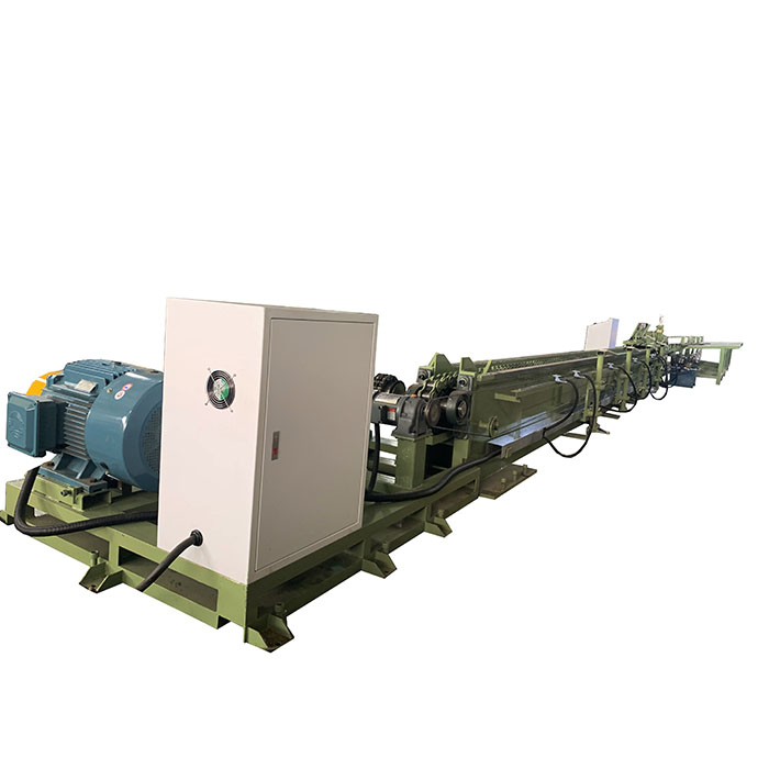
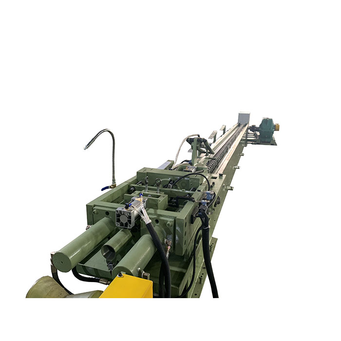
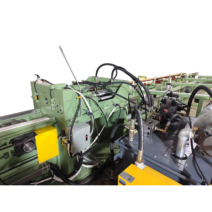
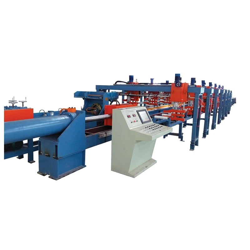
The Automatic Point Pusher Drawing Machine eliminates bar pointing by using a hydraulic push head to feed the full-size bar through the die before the main cylinder takes over. This reduces material loss, tooling, and handling. FR-5T to FR-200T models provide 5–200 tons drawing force and 10–300 tons push force for Ø13–100 mm bars. Suitable for carbon steel, alloy steel, stainless steel, copper, and aluminum.
The Automatic Point Pusher Drawing Machine is a hydraulic cold drawing machine designed for bar production where conventional pointing creates material loss, extra handling, or a bottleneck before drawing. Instead of reducing the bar end with a separate pointing machine, the rear hydraulic push head pushes the unpointed bar through the die until the front end enters the drawing carriage. The carriage then takes over and pulls the bar through the die.
This push-draw arrangement is particularly useful for short bars, high-volume precision bar production, and materials that are difficult or costly to point. FangRong FR-series machines are available from 5T to 200T, covering solid round bars from approximately Ø13 to Ø100 mm. Tube drawing can also be configured with suitable mandrels and tooling.
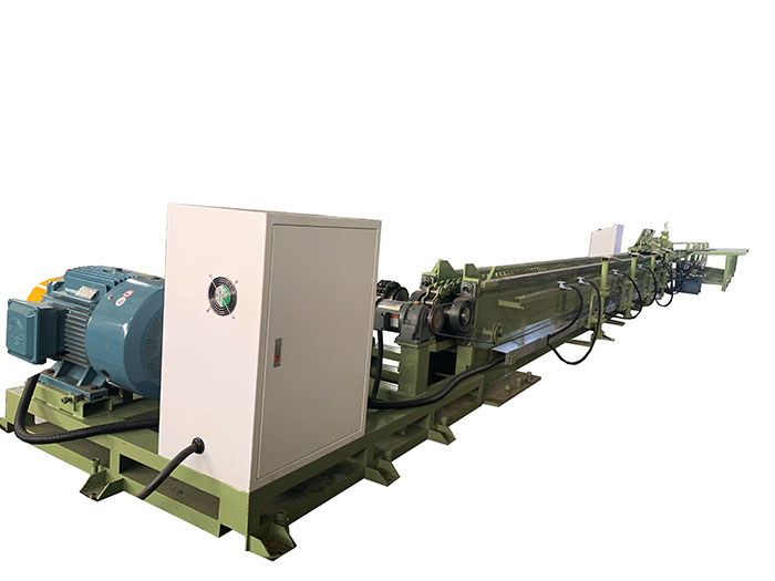
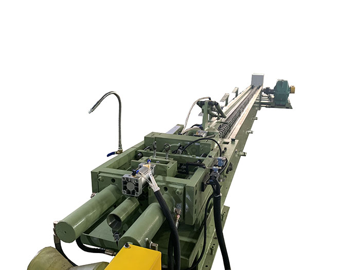
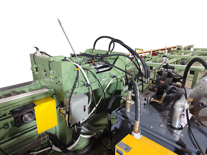
The point pusher drawing machine removes this bottleneck. The unpointed bar is pushed directly into the die, and the drawing carriage takes over after the front end emerges. This is most valuable when material yield and handling time matter more than simply maximizing drawing speed.
Typical production situation: A fastener producer working with short alloy-steel bars may lose a significant amount of usable length during pointing. With a point-pusher system, the bar can enter the drawing process without first machining or swaging its end, allowing more of the purchased bar to remain available for downstream cold heading.
1. Loading: The unpointed bar is placed on the feed rack and aligned with the die.
2. Hydraulic pushing: The rear push head clamps the bar and pushes it forward through the die. This initial force is important because the bar has not been pointed and therefore encounters higher resistance when entering the die.
3. Carriage takeover: When the reduced front end emerges from the die, the main drawing carriage grips the bar.
4. Continuous drawing: The push head releases or returns while the main hydraulic cylinder pulls the bar through the die for the required drawing length.
5. Return and unloading: After drawing, the carriage returns and the finished bar is unloaded for the next operation.
PLC and HMI controls coordinate the push, clamping, drawing and return sequence. The exact push force, drawing force, stroke and die configuration are selected according to the starting diameter, finished diameter, material grade and reduction schedule.
The rear hydraulic push head allows an unpointed bar to enter the die, removing the need for a separate pointing operation. This matters most for plants processing short bars or expensive alloys, where losing material from every bar end directly affects yield.
Production example: A bearing-roller producer using short alloy-steel blanks can retain more usable bar length instead of removing a pointed section before drawing. The economic benefit depends on bar length and the amount normally removed during pointing, so it should be calculated from actual production data rather than assumed as a fixed percentage.
Conventional pointing removes part of the bar end or leaves a reduced section that may later be cut off. The point-pusher process avoids this preparation step. The shorter the bar and the higher its material value, the more important this feature becomes.
For long bars, the percentage saving from eliminating a pointed end may be relatively small. For short precision blanks, however, the same 100-300 mm of material can represent a much larger percentage of the finished part.
The push head provides the force required to start the unpointed bar through the die, while the main drawing cylinder provides the force for the remaining drawing stroke. Push-head capacity is selected according to die-entry resistance, material strength, diameter and reduction rather than simply matching the main drawing tonnage.
Why this matters: A Automatic Point Pusher Drawing Machine can have sufficient nominal drawing tonnage but still be unsuitable if the initial push force is insufficient for a hard alloy or large reduction. FangRong therefore calculates the push and drawing requirements from the customer's actual material and dimensions.
A modular die holder reduces tooling change time when different bar diameters are processed on the same machine. This is especially useful for job shops and plants producing several sizes in one shift. If a line produces only one diameter continuously, quick-change tooling is less critical than correct die life and drawing-force selection.
Hydraulic force and speed can be adjusted according to the material and pass schedule. This allows operators to avoid using excessive force on relatively soft materials while maintaining sufficient force for stainless steel, alloy steel or other high-strength materials.
In precision shaft production, controlled drawing conditions help reduce sudden loading and surface damage. Final straightness and dimensional accuracy still depend on the die design, incoming bar condition, pass schedule and subsequent straightening process.
The PLC controls the sequence between push-head movement, gripping, die entry, carriage clamping, drawing and return. Operators can set and monitor key process parameters through the HMI.
This is most useful when the same machine runs different materials or sizes. For a single-product line, automated sequence control mainly reduces operator intervention and helps keep the established process repeatable.
The standard FR-series configuration is intended for solid round bars. Tube drawing is possible with suitable mandrels, plugs and die arrangements. Tube applications should be confirmed during engineering because wall thickness, mandrel type and lubrication requirements affect the required drawing force and tooling.
The correct model should be selected from the starting diameter, finished diameter, material strength, area reduction and required production output. Nominal tonnage alone is not sufficient for machine selection.
| Model | FR-5T | FR-10T | FR-20T | FR-30T | FR-40T | FR-50T | FR-60T | FR-80T | FR-100T | FR-120T | FR-150T | FR-200T |
| Drawing Capacity (tons) | 5 | 10 | 20 | 30 | 40 | 50 | 60 | 80 | 100 | 120 | 150 | 200 |
| Hydraulic Push Head (tons) | 10 | 20 | 40 | 50 | 60 | 80 | 100 | 120 | 150 | 200 | 250 | 300 |
| Push Cylinder | φ63×200 mm | φ80×200 mm | φ100×200 mm | φ125×200 mm | φ150×300 mm | φ160×700 mm | φ180×300 mm | φ200×300 mm | φ220×300 mm | φ250×300 mm | φ280×300 mm | φ300×300 mm |
| Oil Pump Power (kW) | 5.5 | 11 | 22 | 30 | 37 | 45 | 55 | 75 | 96 | 110 | 132 | 160 |
| Bar Diameter Range (mm) | 13-20 | 15-30 | 15-50 | 20-50 | 25-55 | 30-60 | 30-65 | 35-70 | 35-75 | 40-80 | 45-90 | 50-100 |
| Main Motor Power (kW) | 22 | 37 | 55 | 75 | 90 | 110 | 132 | 166 | 200 | 225 | 300 | 400 |
Standard drawing length: 10 m. Custom drawing lengths can be engineered according to the customer's production layout.
Important: The diameter range shown above is the machine's applicable bar range, not a guarantee that every material can be drawn from the largest starting diameter to every possible finished diameter in one pass. The actual pass schedule must be checked against material strength, reduction per pass, die geometry and lubrication.
Used for bars supplied to cold heading lines for bolts, studs, screws, pins and similar components. The point-pusher design is particularly useful when short blanks create a high percentage of pointing scrap.
Customer scenario: A fastener producer replacing a separate pointing-and-drawing sequence can use the FR-30T to combine die entry and drawing into one machine cycle, reducing intermediate handling before cold heading.
Suitable for precision bar stock used for steering shafts, actuator rods, valve components and other turned or machined parts. The important parameters are drawing force, diameter tolerance, surface condition and the ability to maintain a stable pass schedule.
Customer scenario: An automotive supplier drawing alloy-steel bar for steering components can use an FR-100T configuration where eliminating pointed ends improves material utilization before machining.
Drawing can provide controlled diameter and improved surface condition before subsequent grinding, peeling or finishing. For bearing applications, however, drawing alone does not replace the dimensional and surface requirements of the final grinding process.
Customer scenario: A bearing producer can use the FR-50T for roller blanks where stable drawing reduces the amount of material that must later be removed during finishing.
High-strength tool steels require greater drawing force and careful control of reduction per pass. The machine should therefore be selected from actual material strength and pass-schedule calculations rather than diameter alone.
Customer scenario: A tool-steel processor drawing high-speed steel rods can use a higher-capacity FR model when the deformation resistance exceeds the practical range of smaller drawbenches.
Stainless steel, titanium, nickel alloys and other high-value materials can benefit from eliminating the separate pointing operation. The benefit is especially relevant when the material is expensive or the bar end is difficult to prepare consistently.
Customer scenario: For titanium bar production, avoiding conventional mechanical pointing can simplify the front-end preparation process and reduce material handling before cold drawing.
The Automatic Point Pusher Drawing Machine can be configured for copper and aluminium bar applications where controlled drawing is required for dimensional reduction or surface improvement. Softer materials may not require the maximum available push force, so selecting a smaller model can reduce unnecessary installed power.
Send the following information before requesting a quotation:
Material: grade, tensile strength or yield strength, and heat-treatment condition.
Starting size: outside diameter and bar length.
Finished size: target diameter and dimensional tolerance.
Reduction: required area reduction and number of drawing passes.
Production: required pieces per hour or tonnes per shift.
Product format: solid bar or tube.
Automation: manual loading or automatic feeding, cutting, straightening and stacking.
These details allow the required drawing force, push force, die configuration and machine cycle to be checked before quotation. A machine should not be selected only because its nominal tonnage is higher than another supplier's model.
A standard Automatic Point Pusher Drawing Machine package normally includes the drawbench frame, hydraulic drawing system, hydraulic push head, draw carriage, die holder, hydraulic power unit, electrical control cabinet, PLC and HMI. Standard tooling is supplied according to the agreed configuration; production dies for specific customer dimensions should be confirmed separately in the quotation.
Optional equipment can include automatic feeding, bar measuring, cutting, straightening, unloading and stacking systems. The final scope should be stated item by item in the commercial quotation so that the customer knows exactly what will arrive at the factory.
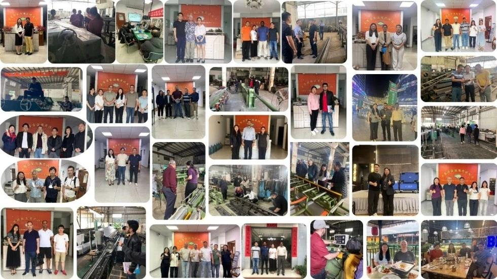
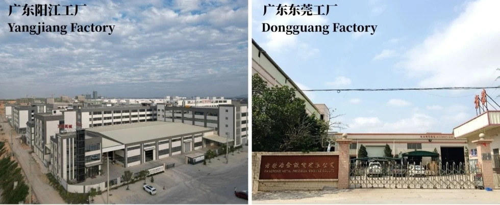
FangRong has manufactured cold drawing equipment since 1998. Production is carried out at facilities in Dongguan and Yangjiang, covering machining, hydraulic assembly, electrical integration and machine testing.
Mechanical alignment: guide rails, draw carriage and die holder are checked for correct alignment before final assembly.
Hydraulic system: pressure stability, cylinder movement and leakage are checked during commissioning.
Electrical system: PLC sequence, HMI functions, sensors and safety circuits are tested.
Drawing performance: where customer material is available, sample bars can be processed to verify the push-draw sequence and the agreed process parameters.
This testing is more useful than a simple no-load demonstration because the actual drawing force depends on the customer's material, starting diameter, reduction and tooling.
1. Engineering review: bar dimensions, material, reduction and automation requirements are reviewed before manufacturing.
2. Component inspection: major structural, hydraulic and transmission components are inspected against production requirements.
3. Precision machining: cylinder and mechanical components are machined and finished according to their functional tolerances.
4. Mechanical assembly: frame, guide system, push head, draw carriage and die holder are assembled and aligned.
5. Hydraulic and electrical integration: cylinders, valves, pumps, sensors, PLC and HMI are connected and commissioned.
6. Functional testing: push, clamp, draw and return sequences are tested before shipment.
7. Final inspection: hydraulic pressure, electrical safety, machine dimensions and agreed configuration are checked.

ISO 9001:2015: quality management system covering relevant design, manufacturing and service processes. Certificate No. UQ231211R1.
CE marking: available for standard machine configurations designed for applicable European machinery requirements. The conformity documentation and applicable standards should be confirmed for the exact machine configuration supplied.
Machinery safety: the machine safety design can incorporate emergency-stop circuits, guards, interlocks and other protective devices required by the applicable machinery risk assessment.
SGS inspection: third-party inspection can be arranged when required by the purchase contract.
Important: CE is not the same as UL certification. If the machine is being installed in the United States or Canada and the project requires UL/CSA-listed electrical components or certification, this must be specified before production so the electrical cabinet and components can be configured accordingly.
MOQ: 1 complete machine.
| Order Quantity | Pricing Basis | Typical Commercial Arrangement |
| 1 machine | Standard quoted price | For individual production lines or trial projects |
| 2-4 machines | Project quantity quotation | Suitable for multi-line expansion; quantity discount can be negotiated |
| 5+ machines | Volume quotation | Final price depends on model mix, automation and delivery schedule |
Standard order lead time: approximately 30-60 days after technical confirmation, contract confirmation and receipt of the agreed deposit. Large machines or systems with integrated automation may require longer production time.
Expedited order: an accelerated schedule can be evaluated according to current factory capacity, machine model and component availability. The expedited lead time must be confirmed in writing before order placement rather than presented as a fixed guarantee.
Payment: a typical arrangement is 30% deposit after order confirmation and 70% balance before shipment after the agreed factory acceptance test. Final terms are subject to the sales contract.
Warranty: 12 months from commissioning under the agreed warranty conditions.
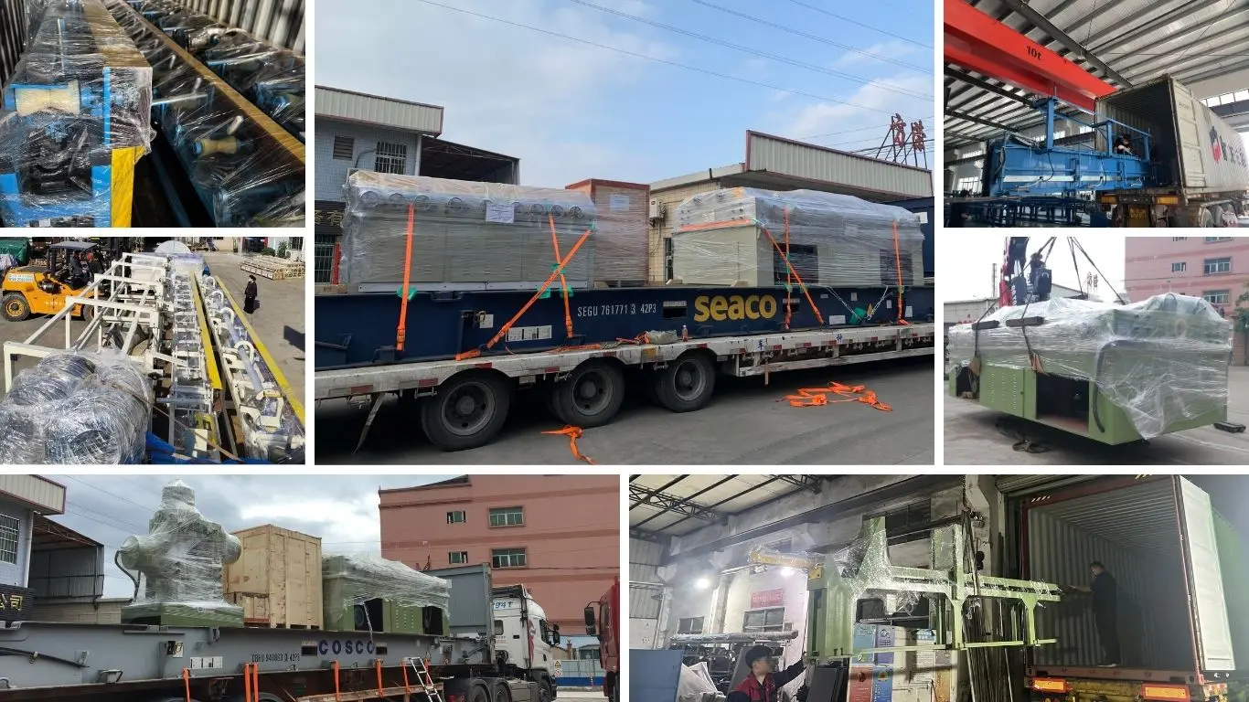
The Automatic Point Pusher Drawing Machine is prepared for export shipment with appropriate protective packaging, corrosion protection for exposed machined surfaces and packing arrangements based on the machine dimensions and shipping method. Large drawbenches may require sectional shipment depending on container limits and site access.
Before shipment, the customer should confirm factory entrance dimensions, foundation requirements, lifting capacity, electrical supply and unloading equipment. Providing these details before production helps prevent installation delays after arrival.
The main advantage is that the bar end does not need to be mechanically pointed before drawing. The rear hydraulic push head pushes the unpointed bar through the die until the leading end emerges, after which the drawing carriage grips and pulls it through. This can reduce material loss and eliminate a separate pointing operation, which is especially useful for high-volume bar production where 100–300 mm of pointed material per bar would otherwise be discarded.
Yes. The Automatic Point Pusher Drawing Machine is designed specifically for drawing bars without conventional pre-pointing. However, the workpiece material, starting diameter, reduction per pass, die geometry, and required drawing force must be checked before confirming the configuration. Very hard alloys or unusually large reductions may require a different die design or pass schedule.
Machine selection should not be based on bar diameter alone. The required drawing force depends on material strength, starting and finished diameters, cross-sectional reduction, friction, die angle, and drawing speed. For example, a 50 mm carbon steel bar and a 50 mm high-strength alloy bar can require significantly different drawing forces. FangRong can calculate the required push and drawing forces from the customer's material and dimensional data before recommending an FR model.
The FR series covers approximately 13–100 mm solid round bars, depending on the model. Typical applications include carbon steel, alloy steel, stainless steel, bearing steel, tool steel, copper, aluminum, and other suitable cold-drawing materials. Tubes or special profiles may require different tooling and should be evaluated separately before ordering.
The saving depends on the original pointing length, bar length, diameter, material, and production method. A conventional process may remove around 100–300 mm from each bar to create a pointed end. Eliminating this step can therefore improve material yield, but the actual saving should be calculated from the customer's bar dimensions and existing pointing allowance rather than assumed as a fixed percentage.
Not necessarily. Cold drawing can improve dimensional accuracy and surface condition, but it should not be considered a substitute for dedicated straightening when tight straightness requirements apply. If the finished product requires controlled straightness, the production line can be configured with a separate straightening process after drawing.
Before quotation, the supplier should receive the material grade, starting diameter, finished diameter, required drawing length, bar length, required output, target dimensional tolerance, drawing passes if known, and available factory power supply. Photos or samples of the existing pointed bar can also help determine die entry conditions and the required push-head configuration.
A standard configuration normally includes the hydraulic power unit, main motor, rear push head, drawing cylinder and carriage, die holder, PLC and HMI control system, and agreed standard tooling. The exact die set, electrical components, automatic loading or unloading system, and other auxiliary equipment should be confirmed in the technical quotation because they depend on the customer's material, dimensions, and automation requirements.
Address
NO.163,Shatong Road,Shabu 2nd Industrial Zone, Dalang Town, Dongguan City, Guangdong, China