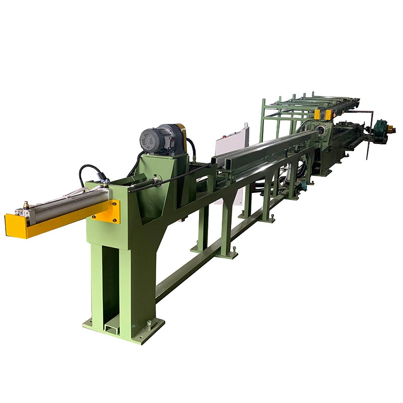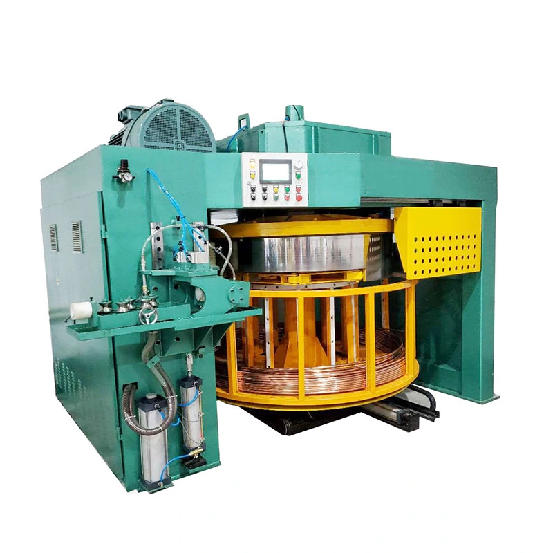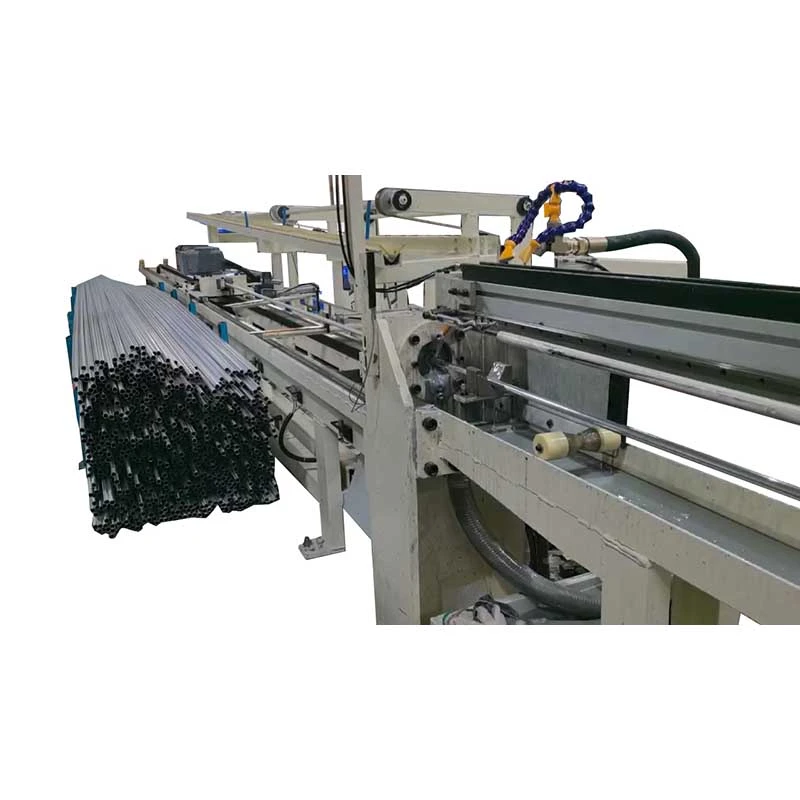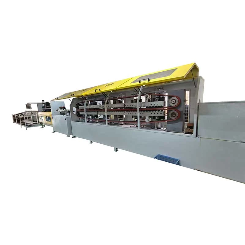

We offer a comprehensive range of precision metal processing equipment, including straightening, cold drawing, pointing, chamfering, cutting, thread rolling machines, and drawing dies, tailored for tube, bar, and wire materials across diverse industries.
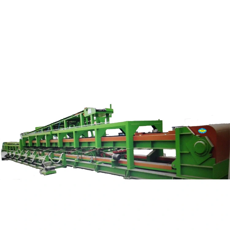
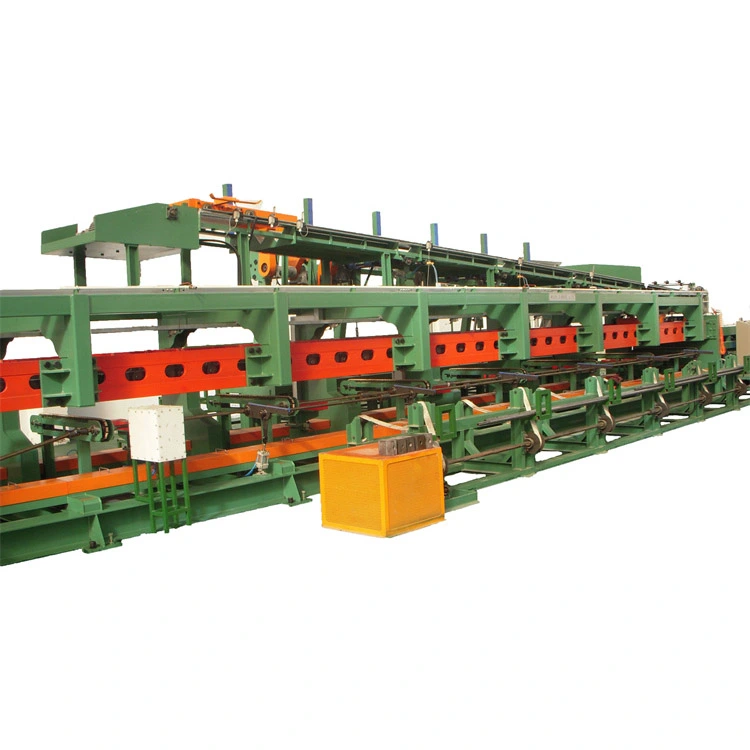
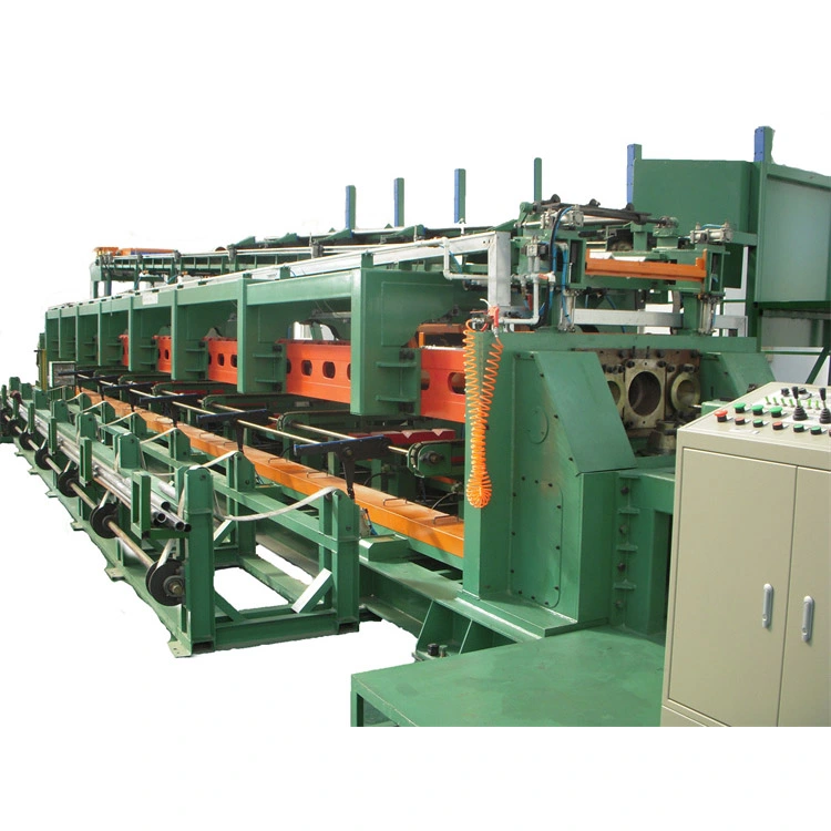
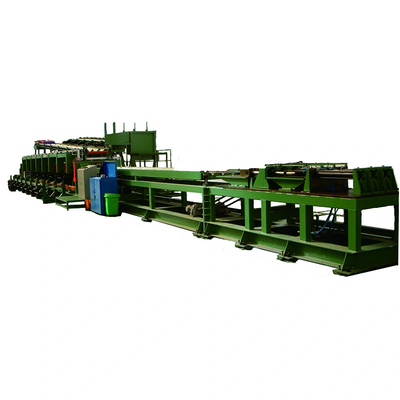
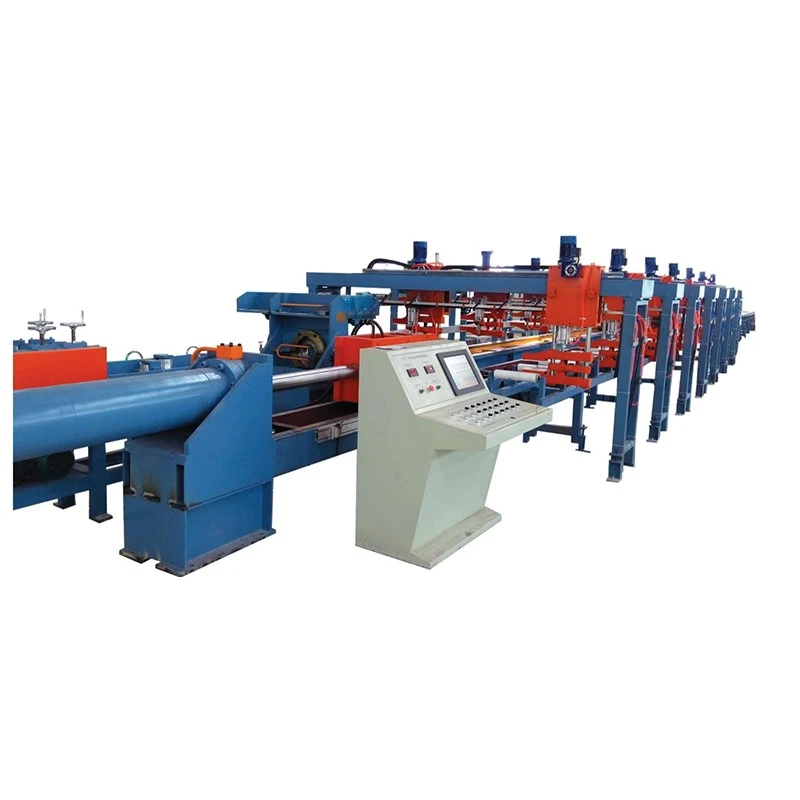
The Automatic Three Lines Cold Drawing Machine processes three tubes or bars simultaneously, making it suitable for higher-volume production without three separate drawbenches. Its double-chain drive balances the pulling load, while automatic feeding, alignment, clamping, and discharge reduce manual handling. FR-16 to FR-90 models offer 15–160 tons of drawing force, 15 m/min speed, and strokes up to 10 m for steel, copper, aluminum, and alloy tubes or bars.
The Automatic Three Lines Cold Drawing Machine is a mechanical multi-strand drawbench designed to draw three tubes or solid bars simultaneously. It is intended for manufacturers that need higher output from one production line without installing three separate drawbenches. The FR series covers 15–160 tons of rated drawing force, with a standard drawing speed of 15 m/min and a 10 m standard stroke. Longer strokes can be engineered for specific production requirements.
The machine is particularly useful for repetitive production of small- and medium-diameter tubes or bars where the same size is produced in batches. For tube drawing, the integrated mandrel system controls the internal diameter and wall thickness. A double-chain drive pulls the carriage from both sides, helping keep the three drawing positions mechanically balanced.

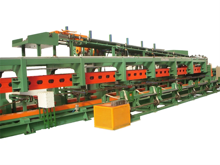
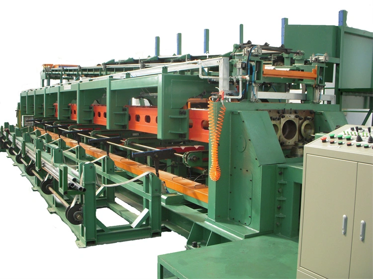
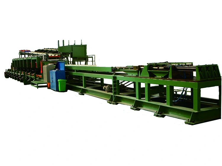
A single-line drawbench processes one workpiece per cycle. When a tube mill or bar producer has a stable, high-volume order for the same specification, adding another single-line machine increases equipment investment, floor space, loading work and maintenance points. The three-line configuration addresses this bottleneck by processing three workpieces during the same drawing stroke.
For example: a copper tube producer making the same small-diameter tube continuously can use three-line drawing instead of running three independent drawbenches. The main productivity gain comes from processing three pieces per stroke; the benefit is much smaller when production involves frequent size changes, low-volume orders or three different specifications at the same time.
Three pointed tubes or bars are loaded onto the feeding system and positioned against their respective dies. The feeding and turnover mechanisms handle workpiece positioning, while the alignment system allows each die position to be adjusted relative to the drawing centre line.
After clamping, the main motor drives the gearbox and double-chain system. The drawing carriage pulls all three workpieces through the dies simultaneously. For tubes, an internal mandrel supports the inside surface during drawing and helps control the final ID and wall thickness. After the drawing stroke, the carriage returns and the finished pieces are discharged for the next cycle.
The PLC coordinates feeding, alignment, clamping, drawing, discharge and carriage return. Optional cut-to-length and stacking systems can be added when the downstream process requires automatic handling.
Production scenario: for a tube manufacturer running long batches of identical hydraulic-cylinder tubes, automatic feeding and synchronized drawing reduce manual loading between strokes. The three strands are processed under the same machine cycle, making the system more suitable for repetitive production than mixed-specification job shops.
1. Three-Strand Synchronous Drawing
Three tubes or bars are drawn in one cycle. This is most valuable when monthly production volume is high and the same or closely matched specification is produced repeatedly. It is less advantageous for frequent changeovers because all three drawing positions are intended to operate with the same drawing setup.
Application example: a copper tube plant producing a standard HVAC tube size can use the three strands continuously instead of adding separate single-line equipment to increase output.
2. Double-Chain Drawing Drive
The carriage is pulled through two sides of the chain drive rather than relying on a single pulling point. Balanced mechanical loading is important when three dies operate simultaneously because uneven carriage loading can affect alignment, die wear and dimensional consistency.
Application example: when three stainless steel tubes are being drawn at the same time, maintaining consistent carriage loading helps reduce differences between the three production positions.
3. Independent Die Alignment
Each drawing position can be fine-adjusted to keep the die centred with the corresponding workpiece. This matters particularly when precise OD, wall thickness or surface requirements leave little allowance for downstream machining.
Application example: in precision hydraulic tubing, accurate die centring is more important than simply maximizing drawing speed because dimensional variation can lead to rejection during subsequent pressure or assembly tests.
4. Internal Mandrel for Tube Drawing
For hollow sections, the mandrel controls the internal geometry during drawing. This is important when the final ID and wall thickness are functional dimensions rather than cosmetic requirements.
Application example: hydraulic cylinder tubes require controlled internal dimensions for piston and seal compatibility, making mandrel selection and pass-schedule calculation part of the machine engineering rather than an optional production detail.
5. Fixed 15 m/min Drawing Speed
The standard drawing speed is 15 m/min. A fixed speed simplifies cycle-time planning and is suitable for production lines where stable throughput is more important than a wide speed range. Material grade, reduction, lubrication and die design still determine whether a particular product can run continuously at the rated speed.
Application example: a high-volume tube line with a stable material grade and pass schedule can use the fixed speed to estimate production capacity and downstream handling requirements before installation.
6. Automatic Feeding, Turnover and Alignment
The feeding motor, turnover motor and alignment system reduce manual handling between drawing cycles. This is particularly useful when long operating hours make repeated manual loading a labour bottleneck.
Application example: a plant operating multiple shifts can automate repetitive loading and workpiece positioning while keeping operators focused on die inspection, lubrication, quality checks and maintenance.
7. Solid Bar and Tube Drawing
The Automatic Three Lines Cold Drawing Machine can be configured for both hollow tubes and solid bars. Tube drawing uses the appropriate mandrel arrangement, while solid-bar production uses solid drawing dies without an internal mandrel.
Application example: a steel processor producing precision bar blanks and seamless tubes can evaluate one machine platform for both applications, provided the tooling and drawing-force requirements are suitable.
8. Optional Downstream Automation
Automatic cutting and stacking can be integrated when the customer needs finished fixed-length pieces rather than long drawn products. These options are most useful when the drawing machine feeds a downstream assembly or packaging process directly.
Model selection should be based on material, starting dimensions, target dimensions, reduction per pass, number of passes, required production volume and calculated drawing force. Do not select a machine only by tube diameter. Harder alloys and larger reductions can require substantially higher drawing force even when the outside diameter is relatively small.
| Model | FR-16 | FR-25 | FR-30 | FR-35 | FR-38 | FR-40 | FR-50 | FR-70 | FR-90 |
| Capacity (tons) | 15 | 20 | 30 | 35 | 50 | 65 | 90 | 120 | 160 |
| Main Motor (kW) | 37 | 55 | 75 | 90 | 132 | 166 | 225 | 315 | DC 400 |
| Gearbox | JZQ650 | JZQ850 | JZQ1000 | ZL100-45 | ZL115-45 | ZL130-45 | P3HS-16-45-D | P3HS-17-45-D | P3HS-18-45-D |
| Turnover Motor (kW) | 2.2 | 2.2 | 2.2 | 2.2 | 2.2 | 2.2 | 2.2 | 2.2 | 2.2 |
| Feeding Motor (kW) | 3 | 3 | 3 | 3 | 3 | 4 | 5.5 | 5.5 | 5.5 |
| Alignment Motor | 0.4 kW | 0.4 kW, 1:150 | 0.4 kW, 1:150 | 0.4 kW, 1:150 | 0.4 kW, 1:150 | 0.4 kW, 1:150 | 1 HP, 1:150 | 1 HP, 1:150 | 1 HP, 1:150 |
| Chain Type | 32A | 2010 bent plate | 2010 bent plate | 2814 bent plate | 3618 bent plate | 4020 bent plate | 4020 bent plate | 4020 bent plate | 5628 bent plate |
| Drawing Speed (m/min) | 15 | 15 | 15 | 15 | 15 | 15 | 15 | 15 | 15 |
| Standard Stroke (m) | 10 | 10 | 10 | 10 | 10 | 10 | 10 | 10 | 10 |
Standard configuration: 3 drawing lines, drawing carriage, double-chain drive, gearbox, main motor, feeding system, turnover system, die alignment system, PLC control and tube mandrel arrangement where required.
Engineering note: the listed tonnage is the machine's rated drawing capacity, not the recommended force for every product. For continuous production, the actual required drawing force, material strength, reduction and lubrication conditions should be checked before model selection.
Used for shock absorber tubes, steering components, drive-shaft-related tubular parts and other repeat-production tube applications. Three-line drawing is most useful when the same specification is produced in large batches.
Production scenario: an automotive supplier can use three simultaneous drawing positions for repeat orders of shock absorber tubes, reducing the number of individual drawing cycles required for a given batch.
Copper and aluminium tubes for heat exchangers and air-conditioning systems are suitable applications when dimensions and material specifications remain stable over long production runs.
Production scenario: a copper tube producer making a standard heat-exchanger tube size can use three-line drawing to increase output without occupying the floor space of three separate drawbenches.
Precision steel tubes for hydraulic cylinders require controlled OD, ID and wall thickness. Mandrel design, die geometry and drawing reduction therefore have a direct effect on the finished tube.
Production scenario: when hydraulic cylinder tubes are subject to pressure testing, controlling dimensional variation between the three strands helps reduce downstream fitting and inspection problems.
The Automatic Three Lines Cold Drawing Machine can be configured for suitable copper and aluminium tubes or solid sections where high-volume repetitive drawing is required. Material condition and required reduction should be confirmed during the pass-schedule calculation.
Stainless steel, alloy steel and other higher-strength materials can be processed when the calculated drawing force and tooling are matched to the material.
Production scenario: a stainless steel tube producer with repeat orders can use the three-line configuration to increase output while maintaining the same die and mandrel setup across all three positions.
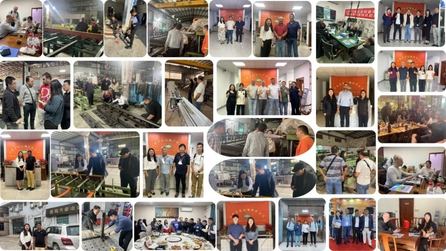
26 Years of Drawbench Engineering
FangRong has been engaged in drawbench engineering since 1998, with experience in mechanical drawing systems, chain drives, die holders, mandrels and production automation.
Two Manufacturing Facilities
Dongguan and Yangjiang facilities support machining, assembly and equipment production. Having more than one production location is particularly useful for projects involving multiple machines or customized automation because manufacturing work can be scheduled in parallel.
Three-Line Alignment Testing
For a multi-strand machine, checking only the unloaded machine is not enough. During factory testing, the drawing mechanism, chain tension, carriage movement and individual die positions should be checked together because dimensional consistency depends on the complete mechanical system.
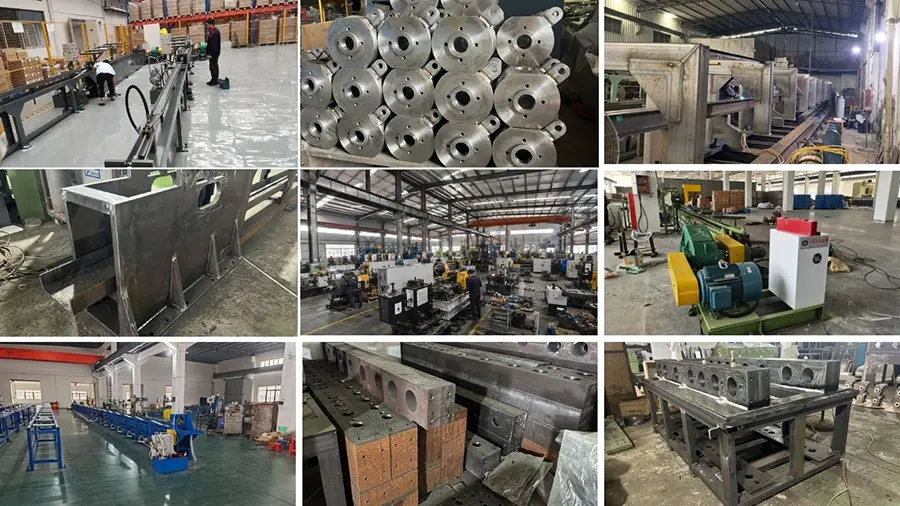
1. Engineering review — Material grade, starting dimensions, target dimensions, reduction schedule, required force, tooling and automation requirements are reviewed before manufacturing.
2. Component inspection — Main structural and transmission components are checked before assembly.
3. Precision machining — Guide rails, die holders, shafts, chain components and other critical parts are machined according to the required mechanical tolerances.
4. Mechanical assembly — Gearbox, sprockets, chains, carriage, tensioning system and die holders are assembled and adjusted.
5. Electrical and PLC integration — Feeding, turnover, alignment and drawing sequences are integrated into the control system.
6. Three-line testing — The three drawing positions are checked for carriage movement, alignment and synchronized operation.
7. Customer sample testing — Where samples are supplied in advance, actual customer material can be used to verify the proposed process and tooling arrangement.
8. Final inspection — Mechanical operation, electrical functions, safety devices, lubrication and key machine dimensions are inspected before shipment.
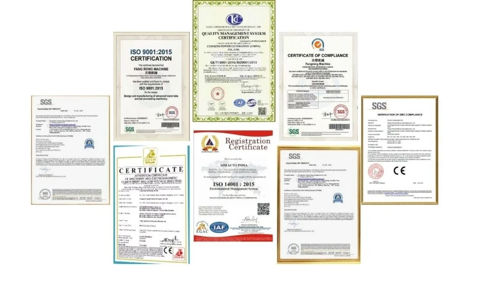
ISO 9001:2015 — Quality management system covering relevant design, manufacturing, installation and service processes. Certificate No. UQ231211R1.
CE compliance — Standard machine configurations are supplied for conformity with applicable EU machinery safety requirements, including the Machinery Directive 2006/42/EC where applicable to the supplied machine and market.
SGS inspection — Third-party inspection can be arranged when required by the buyer, including agreed machine performance and safety inspection items.
UL — UL certification is not listed as a standard certification for the complete FR drawbench. If UL-recognized electrical components or a specific North American electrical specification is required, the electrical configuration should be confirmed before order placement.
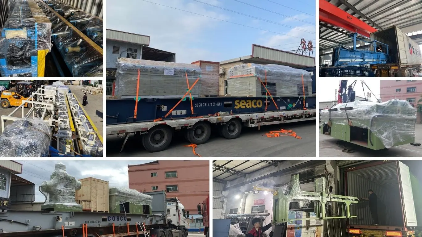
The machine is prepared for export shipment with suitable disassembly, moisture protection and corrosion protection for long-distance transportation. Packing requirements can be adjusted according to container loading, destination climate and project logistics.
MOQ: 1 complete machine/set. Multi-machine orders can be quoted under separate quantity-based pricing.
Quantity-based quotation: 1 set, 2–4 sets, and 5+ sets are quoted separately because the final price depends on model, drawing force, automation, tooling, electrical specification and shipping configuration. Contact FangRong for the current quantity-based price schedule rather than relying on a fixed website price.
FOB: FOB Shenzhen Port, China can be quoted for export orders. The final loading port should be confirmed on the commercial quotation according to the actual shipment arrangement.
Standard order lead time: approximately 30–60 days after technical confirmation, order confirmation and receipt of the agreed advance payment, subject to model and configuration.
Expedited order: urgent production can be evaluated separately based on current factory capacity, component availability and machine configuration. An expedited schedule is confirmed only after FangRong's production department approves the requested delivery date.
Payment: standard commercial terms are 30% deposit and 70% balance before shipment, unless otherwise agreed in the contract.
Warranty: 12 months from commissioning under the agreed warranty conditions.
Normally, no. The three drawing positions are designed to work with the same or compatible tooling and drawing conditions. If your production requires different diameters simultaneously, a separate technical review is necessary because die geometry, mandrel size and required drawing force may differ.
Yes. Tubes are drawn with the appropriate internal mandrel arrangement, while solid bars use solid drawing dies. The tooling and drawing-force calculation must be matched to the material and final dimensions.
Provide the material grade, starting OD and wall thickness, target OD and wall thickness, number of drawing passes, lubrication condition and required output. FangRong can calculate the required drawing force for three workpieces and recommend the appropriate model. Selecting by diameter alone can result in an undersized machine when processing high-strength alloys or heavy reductions.
There is no single reduction value suitable for every material and product. Carbon steel may tolerate a higher reduction than many stainless steels or specialty alloys, but the practical limit depends on material condition, die angle, lubrication, mandrel arrangement and required surface quality. The final pass schedule should be calculated for the actual product rather than using a generic percentage.
No machine configuration can replace correct tooling, material preparation and process control. The three-line system uses balanced carriage pulling and individual die alignment to reduce strand-to-strand variation. Actual dimensional consistency still depends on the material, die and mandrel condition, lubrication and pass schedule.
The standard machine configuration includes the main drawing system, gearbox, double-chain drive, carriage, three-position die arrangement, main motor, feeding and turnover mechanisms, alignment system and PLC control. Product-specific dies, special mandrels, automatic cutting, stacking and other customized equipment should be listed separately in the quotation.
Yes. Expedited production can be evaluated for urgent projects. The achievable delivery date depends on the selected FR model, motor and gearbox configuration, automation requirements, component availability and current production schedule. The expedited date should be written into the order confirmation after factory approval.
Yes, customer samples can be used for process verification when arranged in advance. For a three-line drawbench, sample testing is useful because it allows the proposed die, mandrel, reduction schedule and machine capacity to be checked against the actual material instead of relying only on theoretical calculations.
FangRong provides foundation and anchor-bolt information for the selected machine. The actual foundation should be prepared according to the final approved drawing, including machine length, load, installation position, electrical requirements and access for maintenance.
Yes. Installation supervision, commissioning and operator training can be included in the project scope. Training covers machine operation, die and mandrel changes, routine lubrication, basic troubleshooting and maintenance procedures.
Address
NO.163,Shatong Road,Shabu 2nd Industrial Zone, Dalang Town, Dongguan City, Guangdong, China