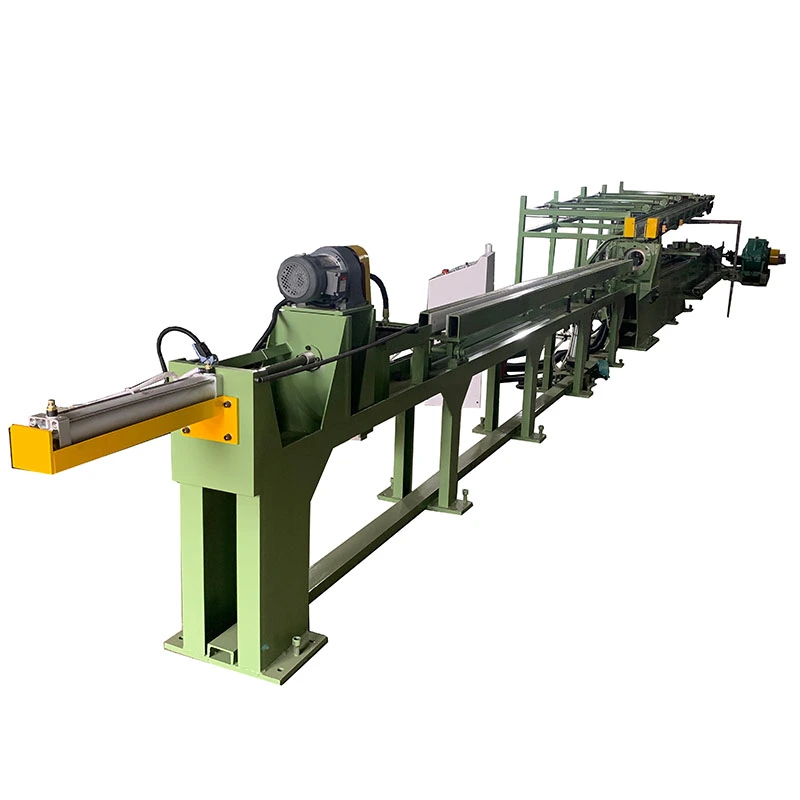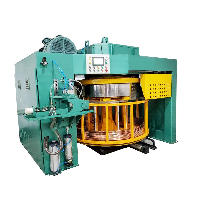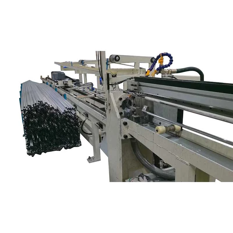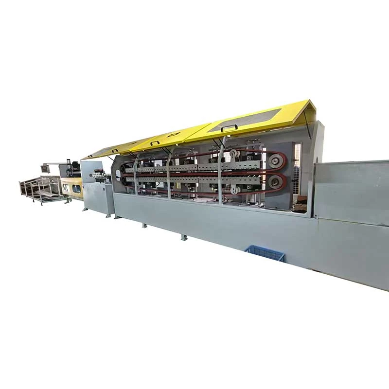

We offer a comprehensive range of precision metal processing equipment, including straightening, cold drawing, pointing, chamfering, cutting, thread rolling machines, and drawing dies, tailored for tube, bar, and wire materials across diverse industries.
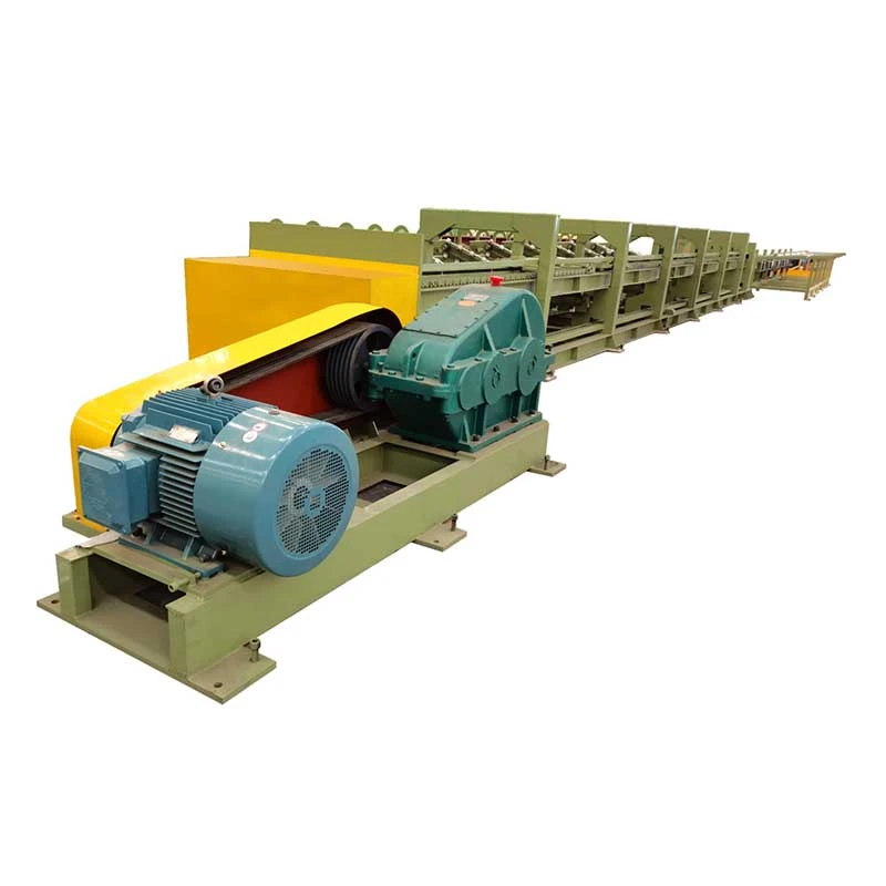
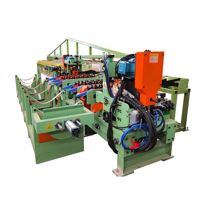
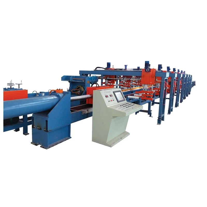
The Automatic Pointing Drawing Straightening Cutting and Chamfering Line integrates pointing, cold drawing, straightening, cutting, and chamfering into one automated process. With hydraulic push-head forces of 10–300 tons and drawing capacities of 5–200 tons, it processes solid round bars from Ø13–100 mm. Automated transfer reduces labor, handling damage, and pointing waste, while centralized PLC control supports consistent production and traceability. Suitable for carbon steel, alloy steel, stainless steel, copper, and aluminum bars used in fasteners, automotive shafts, bearing rollers, and precision components.
The Automatic Pointing Drawing Straightening Cutting and Chamfering Line is a complete bar finishing system for manufacturers that need to turn round bars into drawn, straightened, cut-to-length and chamfered finished bars with minimal manual handling. It combines pointing, cold drawing, straightening, fixed-length cutting and end chamfering in one production line instead of moving bars between five independent machines.
This configuration is particularly useful when surface quality, repeatable dimensions and production traceability matter. Moving long bars manually between separate machines can introduce scratches, dents, orientation errors and inconsistent setup. An integrated transfer system keeps the bar on a controlled process route from raw stock to finished product.
FangRong builds the line around its FR-series push-draw cold drawing machines, with drawing capacities from 5 to 200 tons and hydraulic push-head capacities from 10 to 300 tons. Standard configurations cover solid round bars from Ø13 to Ø100 mm. Depending on the material and reduction ratio, the line can be configured for carbon steel, alloy steel, stainless steel, copper, aluminium and selected specialty alloys.
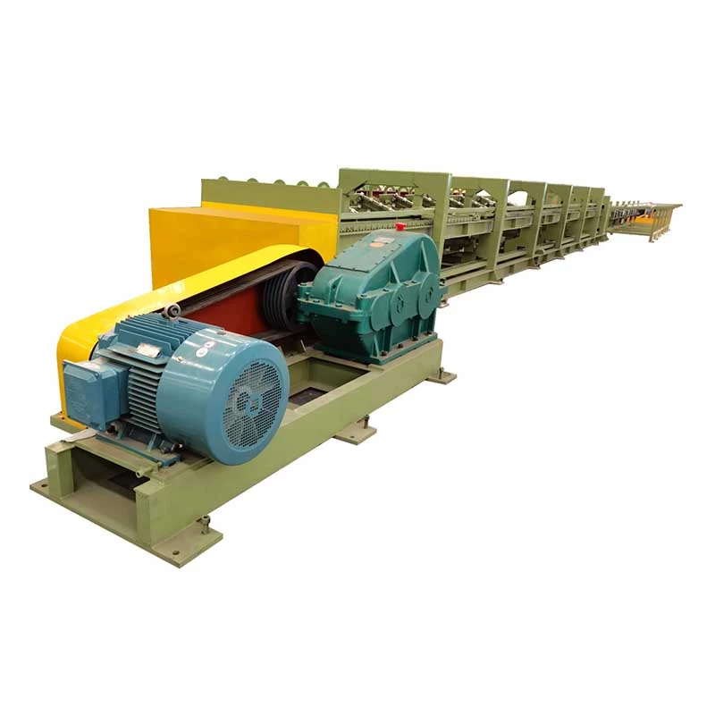
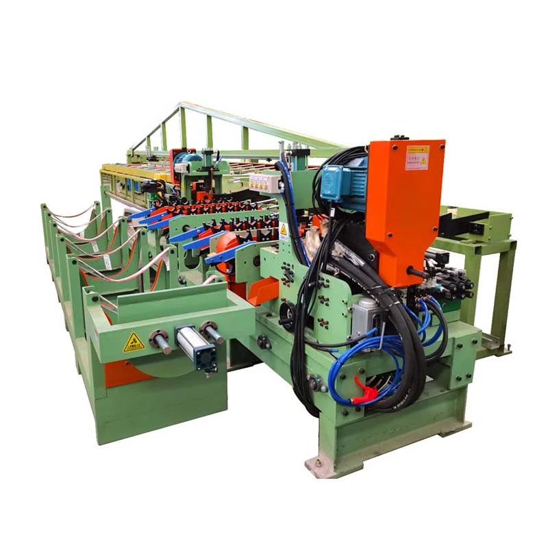
A five-station line is not automatically better than five individual machines. The main advantage appears when the same bar must repeatedly pass through several finishing operations at medium or high production volume.
For example, a fastener manufacturer producing drawn bar for cold heading may need consistent diameter, straightness and cut length before the material enters the heading process. In this situation, combining drawing, straightening and cutting reduces repeated loading and unloading and keeps the production reference consistent.
For a job shop processing many unrelated bar sizes in small batches, separate machines may provide more flexibility. The integrated line becomes more attractive when bar diameter, material grade and finished length are repeated frequently and the cost of manual transfer becomes significant.
1. Pointing: The bar head is reduced to a tapered profile so it can enter the drawing die. The required pointing method depends on the starting diameter, material strength and drawing reduction. Pointing is especially important for hard or large-diameter bars where the leading end must enter the die reliably.
Customer application: When processing alloy steel bars for subsequent cold drawing, consistent head geometry helps prevent failed die entry and reduces the need for operators to repeatedly correct the bar before drawing.
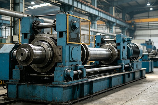
2. Push-draw cold drawing: The hydraulic push head assists the bar through the die during the initial entry stage. Once sufficient material has passed through the die, the drawing carriage clamps the reduced end and completes the drawing stroke. This arrangement is useful for larger bars or higher-strength materials where initial die-entry resistance is considerable.
Parameter that matters: Drawing tonnage should not be selected from bar diameter alone. Material strength, reduction per pass, die geometry, lubrication and target diameter all affect the required drawing force. A larger machine is not necessarily the better choice if the actual force requirement is much lower.
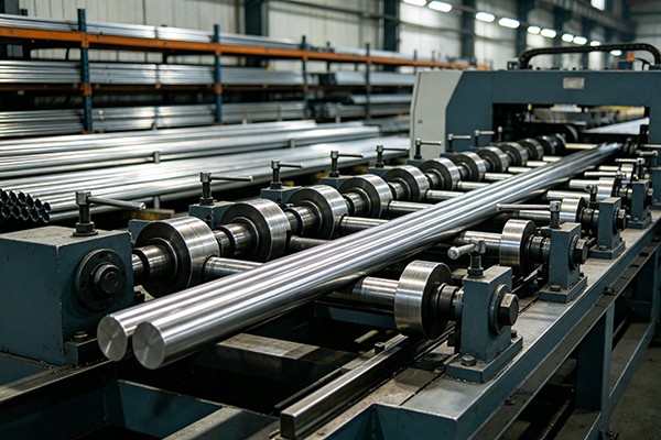
3. In-line straightening: After drawing, the bar passes directly to the straightening section. Multi-roll or two-roll configurations can be selected according to diameter, material and required straightness. The commonly specified target is ≤0.3 mm/m, subject to the material, incoming condition and final process requirements.
Customer application: For linear-motion shafts and precision component stock, straightness is more important than simply achieving the target diameter. A controlled in-line straightening process can reduce the amount of secondary correction required before machining.
4. Fixed-length cutting: The PLC controls the cutting position according to the programmed finished length. Saw or shear cutting can be selected according to material, diameter, required end condition and production rate.
Parameter that matters: If bars are supplied directly to CNC machining or cold heading, cutting tolerance and end condition can affect downstream setup. For rough stock preparation, an extremely tight cutting tolerance may add cost without providing a practical production benefit.
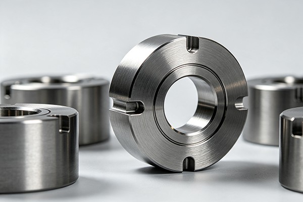
5. End chamfering: The finished bar ends are chamfered to remove sharp edges and prepare the material for handling, assembly or subsequent machining. Internal, external or combined chamfering can be configured according to the customer's drawing.
Customer application: In shaft and fastener production, a controlled chamfer can improve component feeding and reduce the risk of burr-related problems during assembly or subsequent machining.
Complete material flow: Raw bar → automatic loading → pointing → drawing → straightening → fixed-length cutting → chamfering → automatic stacking.
Too much manual transfer: When five operations are separated, bars must be repeatedly unloaded, aligned and reloaded. Automatic transfer reduces handling between stations and is particularly valuable for long bars or finished surfaces that are easily scratched.
Unstable downstream straightness: Drawing alone does not guarantee the final straightness required by a machining or assembly process. An in-line straightener provides a dedicated correction stage immediately after drawing.
Inconsistent finished lengths: Manual measuring and cutting can create variation between batches. PLC-controlled length positioning gives the operator a repeatable production reference.
Separate production records: With independent machines, material may be transferred between different production orders or operators. Centralized control allows drawing, straightening, cutting and chamfering parameters to be managed as one production recipe.
High labour input: The integrated line is designed for one operator to supervise the production cycle rather than requiring a dedicated operator at every station. Actual staffing depends on loading, packaging and factory automation requirements.
Integrated five-process production: Pointing, drawing, straightening, cutting and chamfering are connected into one process route. This is most valuable for repetitive production where the same sequence is used continuously.
Push-draw configuration: The hydraulic push head helps overcome initial die-entry resistance before the main drawing carriage takes over. This becomes more important as bar diameter, material strength or drawing reduction increases.
Ø13–Ø100 mm bar range: The available FR models cover different diameter ranges. Selecting a model should be based on the actual starting diameter and drawing force rather than simply choosing the largest available diameter range.
In-line straightening: The straightener is selected according to bar diameter, material yield strength, drawing condition and required straightness. For general stock preparation, extreme straightness specifications may not be necessary; for shafts and precision components, they can directly affect machining allowance and rejection rates.
Automatic cutting: PLC-controlled length setting reduces repetitive manual measurement. Saw and shear solutions can be evaluated according to bar material, diameter, production speed and required cut-end quality.
Automatic chamfering: Chamfer dimensions can be specified according to the downstream machining or assembly requirement. The chamfering unit should be sized together with the cutting station rather than treated as an independent accessory.
Centralized PLC and HMI: The control system coordinates station timing, transfer, drawing cycles, cutting length and safety interlocks. Recipe-based operation is useful when the same factory processes several standard bar specifications.
The following FR-series specifications refer to the core drawing station. The pointing, straightening, cutting, chamfering and transfer systems are engineered according to the finished product requirements.
| Model / Parameter | FR-5T | FR-10T | FR-20T | FR-30T | FR-40T | FR-50T | FR-60T | FR-80T | FR-100T | FR-120T | FR-150T | FR-200T |
| Hydraulic Push Head Tonnage (tons) | 10 | 20 | 40 | 50 | 60 | 80 | 100 | 120 | 150 | 200 | 250 | 300 |
| Cylinder Diameter × Stroke (mm) | φ63×200 | φ80×200 | φ100×200 | φ125×200 | φ150×300 | φ160×700 | φ180×300 | φ200×300 | φ220×300 | φ250×300 | φ280×300 | φ300×300 |
| Oil Pump Power (kW) | 5.5 | 11 | 22 | 30 | 37 | 45 | 55 | 75 | 96 | 110 | 132 | 160 |
| Bar Material Range (mm) | 13–20 | 15–30 | 15–50 | 20–50 | 25–55 | 30–60 | 30–65 | 35–70 | 35–75 | 40–80 | 45–90 | 50–100 |
| Main Motor Power (kW) | 22 | 37 | 55 | 75 | 90 | 110 | 132 | 166 | 200 | 225 | 300 | 400 |
Important: Hydraulic push-head tonnage is not the same as drawing capacity. The final model should be selected from the calculated drawing force for the actual material, starting diameter, finished diameter, reduction ratio and lubrication condition.
Standard drawing length is approximately 10 m; longer or special stroke configurations can be engineered. All models in this table are intended for solid round bars.
For small-diameter carbon steel bars: A smaller FR model is normally sufficient when the reduction and material strength result in a relatively low drawing force. Oversizing the hydraulic system increases investment and power requirements without necessarily improving product quality.
For stainless steel: Drawing force and work hardening become more important. The die material, lubrication method, reduction per pass and drawing speed should be evaluated together with machine tonnage.
For large alloy steel bars: Hydraulic push capacity and structural rigidity become critical because initial die entry can require substantial force. Model selection should be based on an engineering force calculation rather than diameter alone.
For precision shafts: The drawing machine is only one part of the tolerance chain. Straightening capability, cut-length tolerance, chamfer dimensions and material condition should all be specified before ordering.
For high-volume production: Automatic loading, transfer and stacking become more important than simply increasing drawing speed. The real production target should be evaluated as finished bars per hour, including transfer and cutting time.
The Automatic Pointing Drawing Straightening Cutting and Chamfering Line can prepare drawn bar for bolts, studs, pins and other cold-heading components where diameter consistency, straightness and controlled cut length affect the downstream forming process.
Typical production scenario: A fastener producer running repeated carbon or alloy steel grades can use automatic pointing and drawing followed by in-line straightening and cutting, reducing repeated handling before the bar enters cold-heading preparation.
Applications include shaft stock, steering components, piston rods, valve-related components and other precision bar products.
Typical production scenario: For a shaft manufacturer supplying CNC machining lines, automatic cut-to-length control can reduce manual measuring before machining, while straightening helps maintain a more consistent machining allowance.
For bearing rollers, guide shafts and similar products, straightness and dimensional consistency are often more important than simply achieving maximum drawing speed.
Typical production scenario: A bearing-component producer can configure the line around a repeatable diameter and finished-length specification, allowing drawing, straightening and cutting to be performed without moving bars to separate machines between operations.
Titanium, nickel-based and other specialty alloys require closer attention to drawing force, work hardening, tooling, lubrication and surface protection. These applications should be evaluated using actual material grades and reduction schedules before machine selection.
Typical production scenario: When expensive alloy bar must maintain surface integrity through several finishing stages, automated transfer reduces unnecessary contact points and allows the process parameters to remain tied to the same production order.
High-speed steel and tool steel bars can require high drawing forces and careful control of deformation. The integrated cutting and chamfering stations are useful when finished blanks are supplied directly to machining operations.
Typical production scenario: A tool-steel processor producing repeated blank lengths can eliminate a separate post-cut deburring operation when the required chamfer is incorporated into the line.
Copper and aluminium have different deformation and surface requirements from steel. Die geometry, lubrication and straightening pressure should therefore be configured for the specific alloy rather than copied from a steel-bar setup.
Typical production scenario: For connector or conductive-bar stock, maintaining the specified diameter and surface condition may be more important than maximum drawing force, so the line can be configured around dimensional control and gentle transfer.
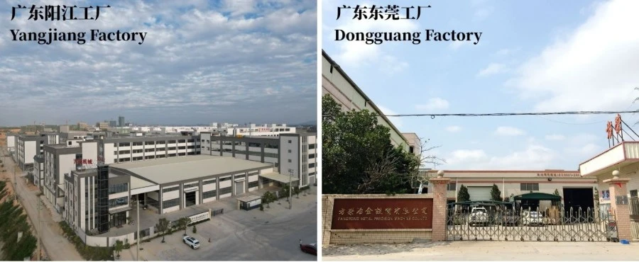
Dongguan Fangrong Metallurgical Equipment Co., Ltd. operates its main manufacturing base in Dongguan, while Yangjiang Fangrong Machinery Co., Ltd. provides additional production capacity. The facilities manufacture cold drawing, straightening and related metal forming equipment.
Before production, the Automatic Pointing Drawing Straightening Cutting and Chamfering Line is determined from the customer's material grade, starting diameter, finished diameter, finished length, reduction ratio, straightness requirement, cutting tolerance, chamfer geometry and target output. This information determines machine tonnage, die arrangement, straightener type and automation layout.
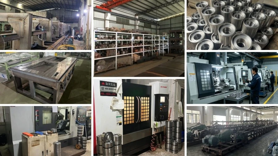
Manufacturing and inspection: Hydraulic components, cylinder assemblies, structural parts, die holders, straightening rolls and transfer mechanisms are machined and assembled before the complete line is integrated. Hydraulic circuits are pressure-tested, while mechanical alignment and electrical functions are checked before shipment.
Factory acceptance testing: The complete line can be tested with customer-supplied bar samples when available. The practical acceptance points should include drawing performance, transfer reliability, straightness, finished length, chamfer dimensions, safety interlocks and automatic cycle stability—not simply whether the machine can run without load.
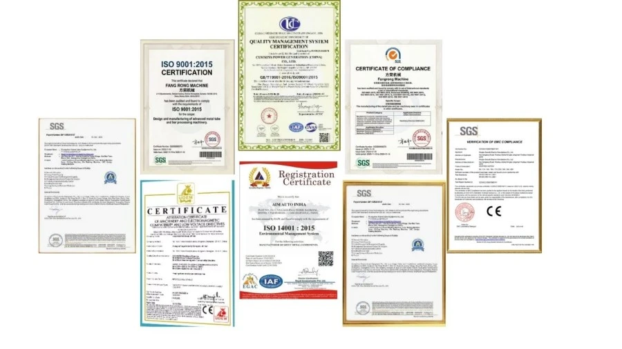
ISO 9001:2015: Quality management system covering the company's design, manufacturing and service processes. Certificate No. UQ231211R1.
CE: Standard FR equipment is supplied for applicable European machinery requirements. For EU projects, the final machine configuration and Declaration of Conformity should be checked against the applicable legislation and harmonized standards for the supplied equipment.
Machinery safety: Safety functions such as emergency stops, guarding and interlocks are incorporated according to the final machine configuration. The exact applicable EN/ISO safety standards should be confirmed in the technical documentation supplied with the machine.
SGS inspection: Third-party inspection can be arranged when required by the purchasing contract or project specification.
Patents: FangRong states that it holds invention and utility model patents covering components and mechanisms used in its metal forming equipment.
MOQ: 1 complete production line. The Automatic Pointing Drawing Straightening Cutting and Chamfering Line is engineered and manufactured according to the customer's bar specifications, so one set is sufficient for a complete project.
Quantity-based quotation: For project purchasing, quotations can be structured by 1 set, 2–3 sets, and 4+ sets. The actual unit price for each quantity tier should be confirmed in the commercial quotation because the configuration, tooling and automation level can materially change the equipment cost.
FOB term: FOB Shenzhen Port, China can be used for export quotations when applicable. The final port, packing specification, inland transportation and export charges should be stated explicitly on the proforma invoice and sales contract.
Standard order lead time: approximately 60–90 days for standard configurations such as FR-5T to FR-60T, subject to final technical confirmation and production schedule.
Heavy-duty standard order: approximately 90–150 days for FR-80T and larger configurations, depending on machine size, automation and testing requirements.
Urgent order: An accelerated production schedule can be requested before order confirmation. The expedited lead time is project-specific and should be confirmed after checking component availability, factory capacity and the required FAT schedule. An urgent order should not be quoted with an assumed delivery date before these items are confirmed.
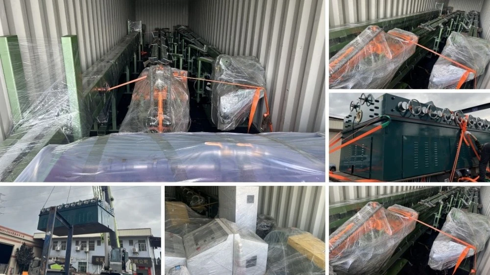
The line is prepared for export shipment with sectioned equipment packed according to transport dimensions. Wooden cases, moisture protection and corrosion protection are used where required by the machine configuration and shipping route. Final packing dimensions and container loading plans are confirmed after the line layout is finalized.
Yes. The standard concept connects all five operations through automatic transfer and centralized PLC control. However, loading of raw bars, removal of finished bundles and material replenishment may still require operator involvement depending on the selected loading and stacking system.
Do not select the machine from bar diameter alone. The required drawing force depends on material grade, starting diameter, finished diameter, reduction per pass, die angle, lubrication and drawing speed. Provide these parameters to FangRong for a force calculation before selecting the FR model.
The push head and pointing station perform different functions. The push head provides axial force to assist die entry, while pointing reduces the bar end to a geometry that can enter the die. The need for a particular pointing method depends on the starting bar diameter, material and die configuration. Pointing scrap should therefore be evaluated separately rather than assuming that push-draw operation eliminates it.
The standard target stated for the in-line straightener is ≤0.3 mm/m. Actual achievable straightness depends on bar material, diameter, incoming condition, drawing condition and straightener configuration. For critical shaft or precision applications, the acceptance method and measurement length should be agreed before production.
Yes, subject to engineering confirmation. These materials normally require greater drawing force and more attention to work hardening, lubrication, die selection and reduction per pass. The material grade should be provided before the machine is sized.
Yes, within the designed operating range. Diameter changes normally require corresponding tooling and setup changes, while finished length can be programmed through the PLC within the machine's cutting and handling limits. If many diameters are mixed in daily production, tooling-change time should be included in the production-capacity calculation.
Cutting accuracy depends on the cutting method, bar diameter, material, measuring system and required tolerance. The finished-length tolerance should be specified on the technical agreement instead of relying on a general statement such as "high precision."
Yes. Transfer direction, loading height, finished-bar stacking, upstream stock preparation and downstream machining interfaces can be considered during layout engineering. Providing the existing line layout and material-flow direction at the quotation stage helps avoid costly modifications after installation.
Provide the material grade, starting diameter, finished diameter, bar length, finished length, required straightness, chamfer size, annual or hourly output, existing upstream equipment, power supply and preferred automation level. A sample drawing or finished-product drawing is useful for defining the cutting and chamfering stations.
The typical scope includes the pointing station, push-draw drawing machine, hydraulic power unit, drawing carriage, in-line straightener, automatic cutting unit, chamfering unit, transfer mechanisms and PLC/HMI control system. Dies and special tooling should be listed separately in the quotation so the buyer can clearly identify the complete project cost.
The MOQ is 1 complete production line. Quantity-based quotations can be prepared for 1 set, 2–3 sets and 4+ sets. The actual price at each quantity level depends on the final machine configuration and tooling.
Standard configurations generally require 60–90 days. Larger FR-80T and above projects normally require 90–150 days. For urgent projects, an accelerated schedule can be evaluated before contract signing based on component availability and current factory capacity.
Yes. FOB Shenzhen Port, China can be quoted when applicable. The quotation should clearly state the FOB port, packing scope, inland transport responsibility and any excluded charges so the buyer can compare offers on the same basis.
The standard warranty is 12 months from commissioning. Installation supervision, commissioning, operator training, spare-parts support and remote troubleshooting can be included according to the contract. The exact response method and spare-parts scope should be stated in the sales agreement.
Yes. Testing with customer-supplied material is recommended for projects involving difficult alloys, tight straightness requirements or special chamfer geometry. It allows the drawing force, tooling, straightening setup, cutting and finished surface to be evaluated before shipment.
The buyer should check more than machine movement. A practical FAT should cover drawing force and cycle stability, bar transfer, dimensional reduction, straightness, finished length, chamfer dimensions, hydraulic leakage, electrical functions and safety interlocks. For critical products, finished samples should be measured against the agreed acceptance specification.
The required foundation depends on the line length, machine weight, drawing force and site conditions. FangRong can provide foundation and anchor-bolt drawings after the final equipment layout is confirmed. The civil foundation should be completed according to the approved drawing before installation.
Yes. Common customization areas include bar diameter range, drawing stroke, die holder, straightener configuration, cutting method, chamfer geometry, transfer system, loading and stacking, PLC communication and finished-bar handling. Customization should be finalized from the actual production process rather than adding unused functions.
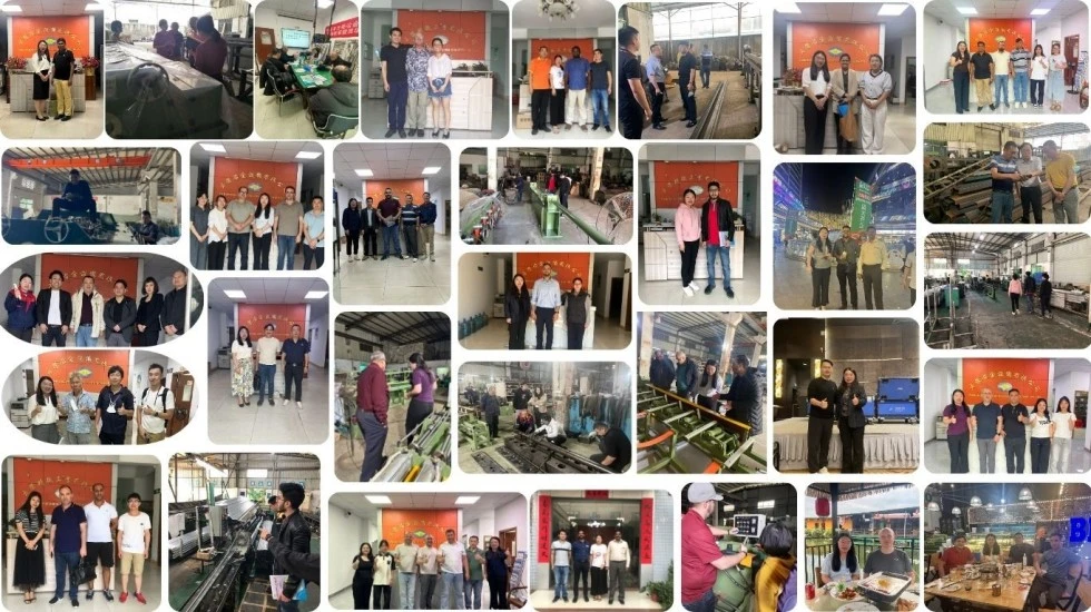
Drawbench engineering since 1998: FangRong has focused on cold drawing and related metal forming equipment for more than two decades. The company states that its equipment has been supplied to customers in more than 70 countries.
Integrated process engineering: The project is not limited to supplying a drawbench. Drawing force, die arrangement, straightening, cutting, chamfering and material transfer need to work together; this is particularly important when the customer wants one finished bar to pass through all operations without intermediate storage.
Two manufacturing facilities: Dongguan and Yangjiang production facilities provide additional manufacturing capacity for large or multiple-machine projects.
Application-based testing: Where possible, testing with the customer's actual bar material provides more useful evidence than an unloaded machine demonstration. This is especially relevant for stainless steel, high-strength alloy steel and tight-tolerance applications.
Engineering support after delivery: Installation supervision, commissioning, operator training, spare-parts support and remote troubleshooting can be included according to the project scope.
For an accurate machine selection and quotation, send the material grade, starting diameter, finished diameter, finished length, required straightness, chamfer dimensions and target output. These parameters are enough for the engineering team to determine the appropriate FR model and integrated line configuration.
Address
NO.163,Shatong Road,Shabu 2nd Industrial Zone, Dalang Town, Dongguan City, Guangdong, China