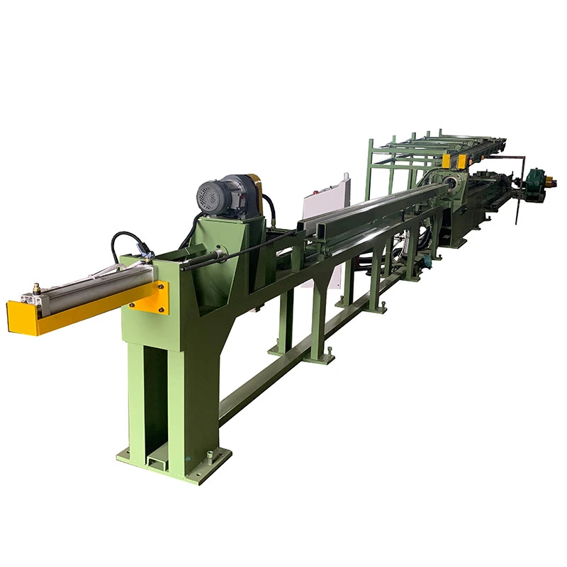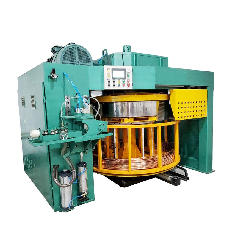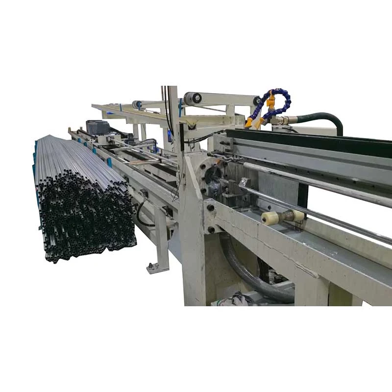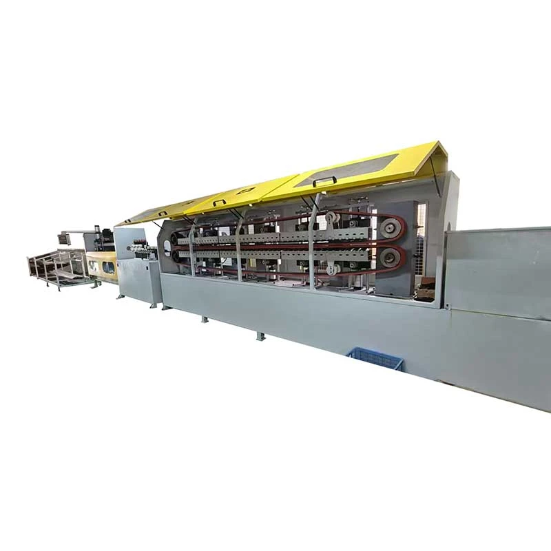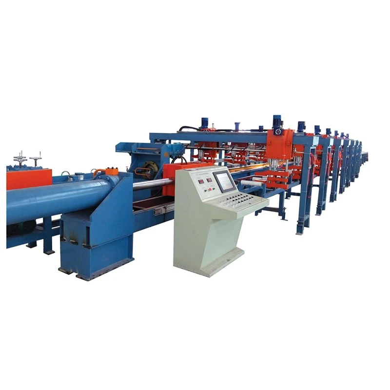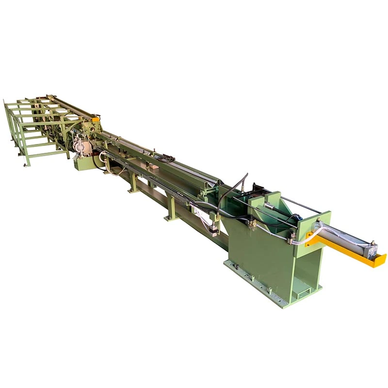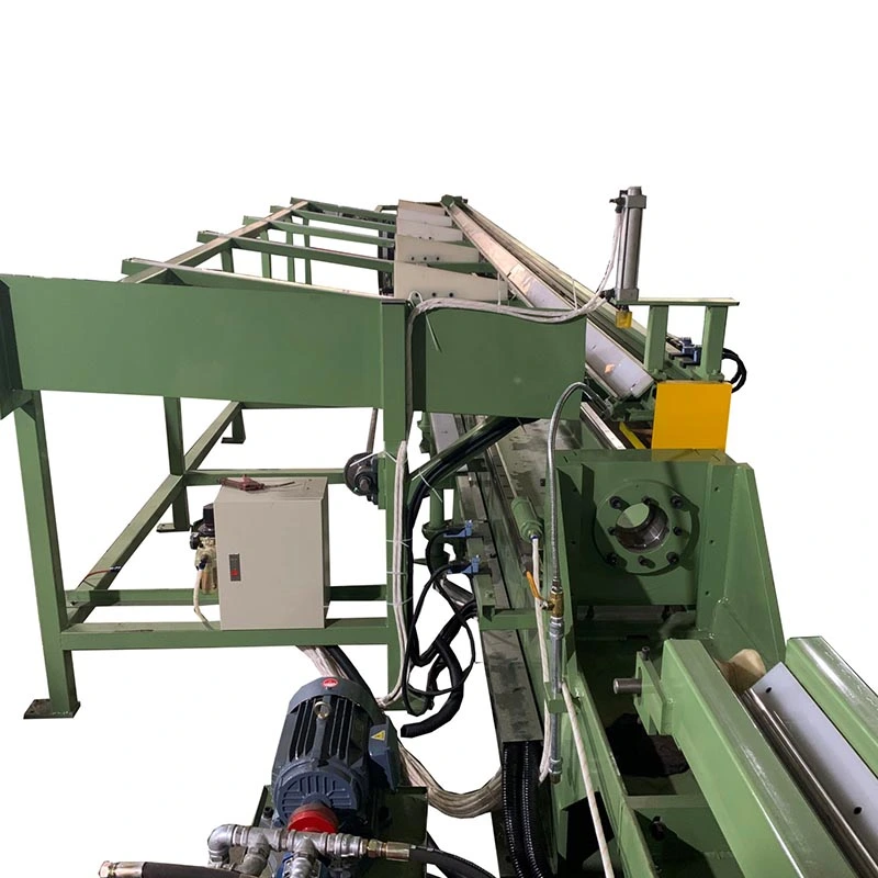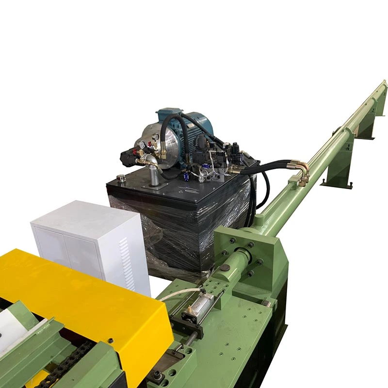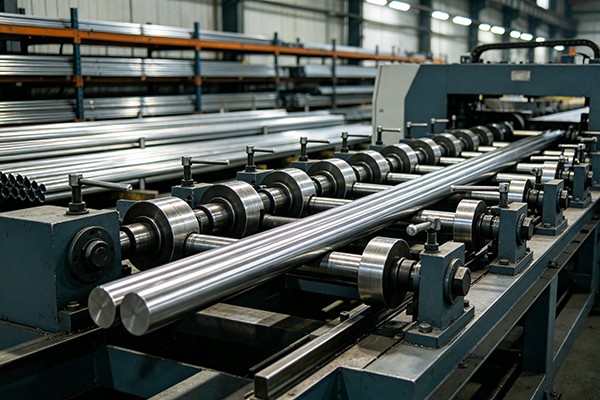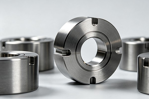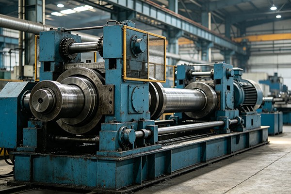

We offer a comprehensive range of precision metal processing equipment, including straightening, cold drawing, pointing, chamfering, cutting, thread rolling machines, and drawing dies, tailored for tube, bar, and wire materials across diverse industries.
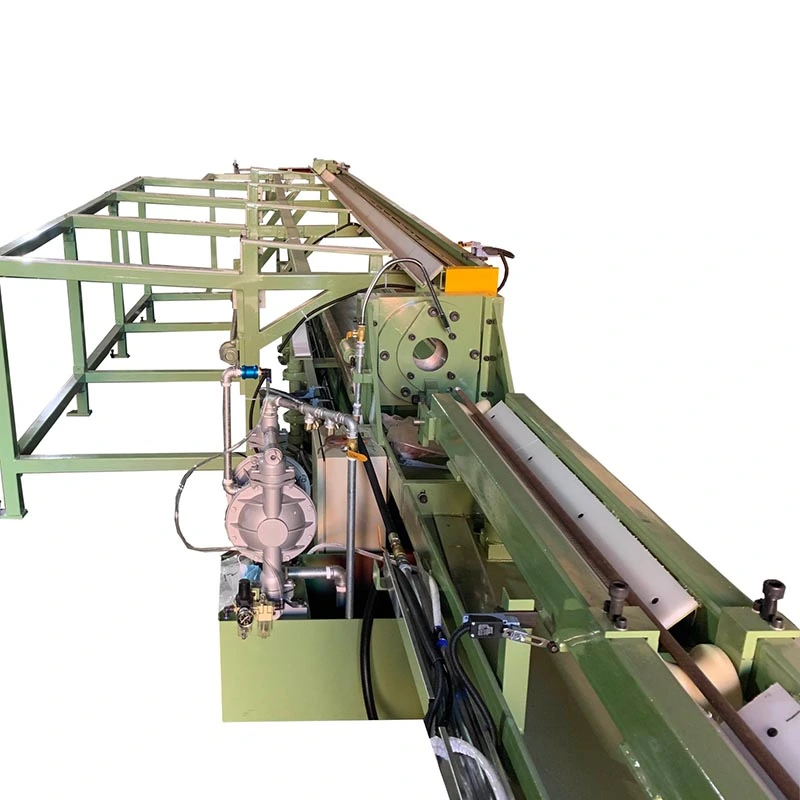
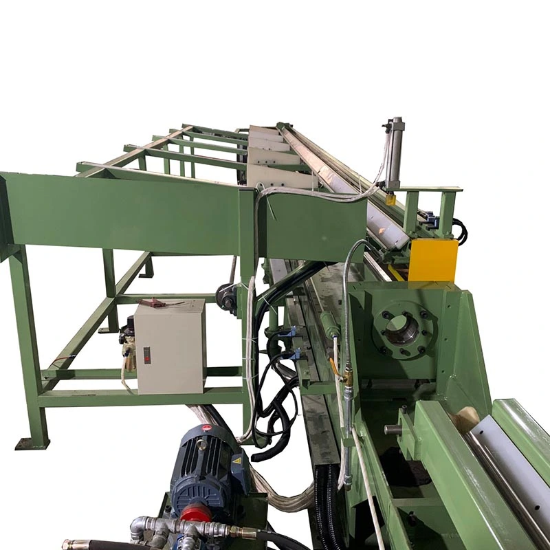
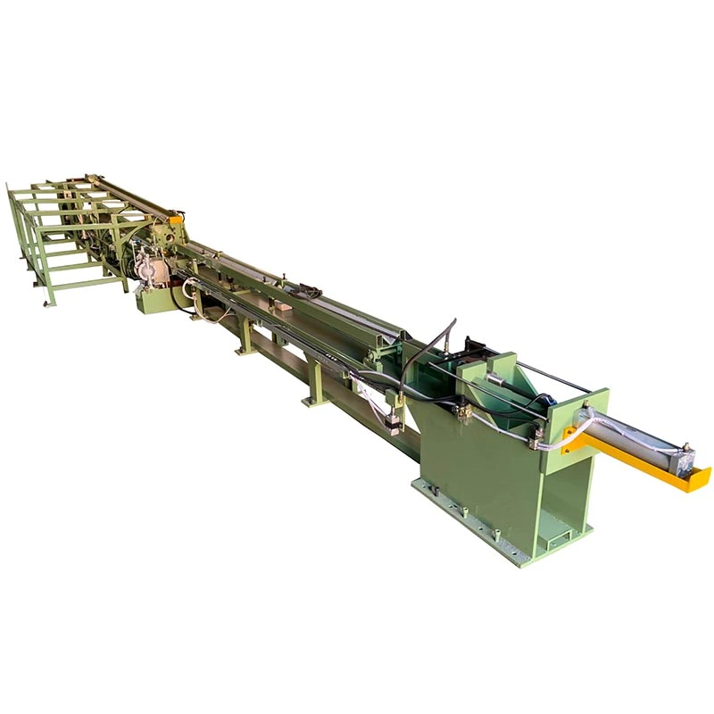
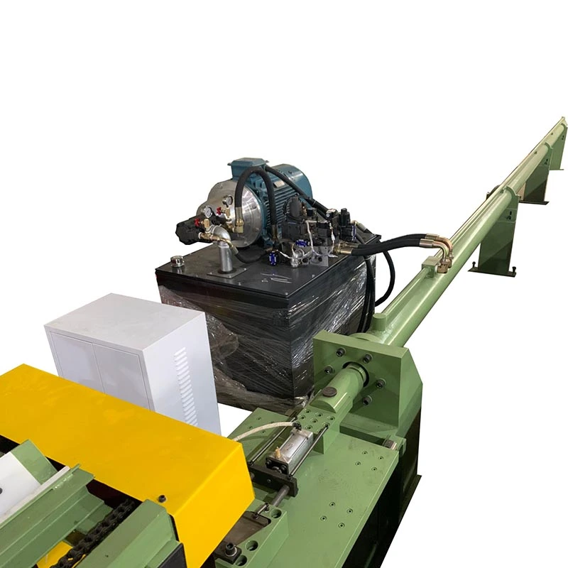
The Pipe Hydraulic Cold Drawing Machine reduces the outside diameter of metal tubes while controlling wall thickness and internal dimensions through a controlled cold drawing process. A hydraulic cylinder pulls the tube through a drawing die, while the selected plug or mandrel controls the internal geometry.
The machine is suitable for production where hot-rolled, extruded, or other incoming tubes need tighter dimensional control before machining, honing, bending, or final assembly. The actual drawing configuration is selected from the required finished diameter, wall thickness, internal accuracy, material, reduction per pass, and production length.
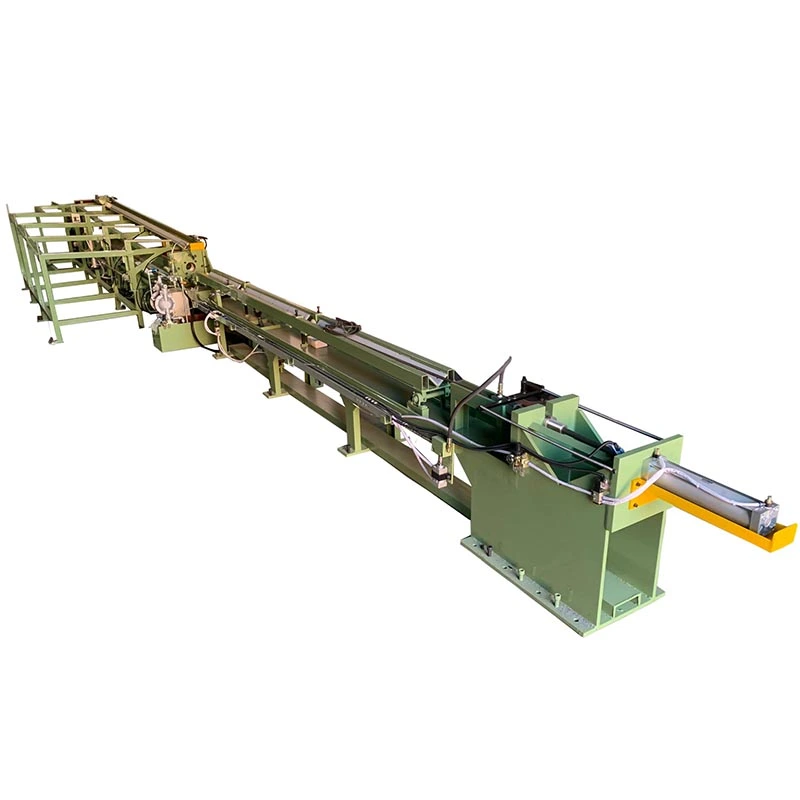
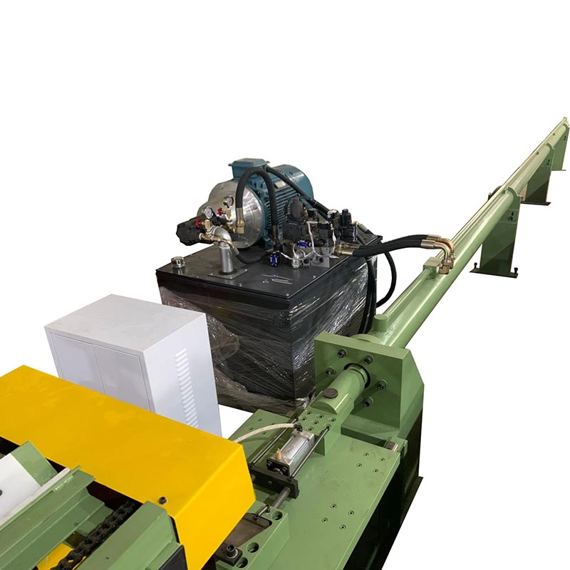
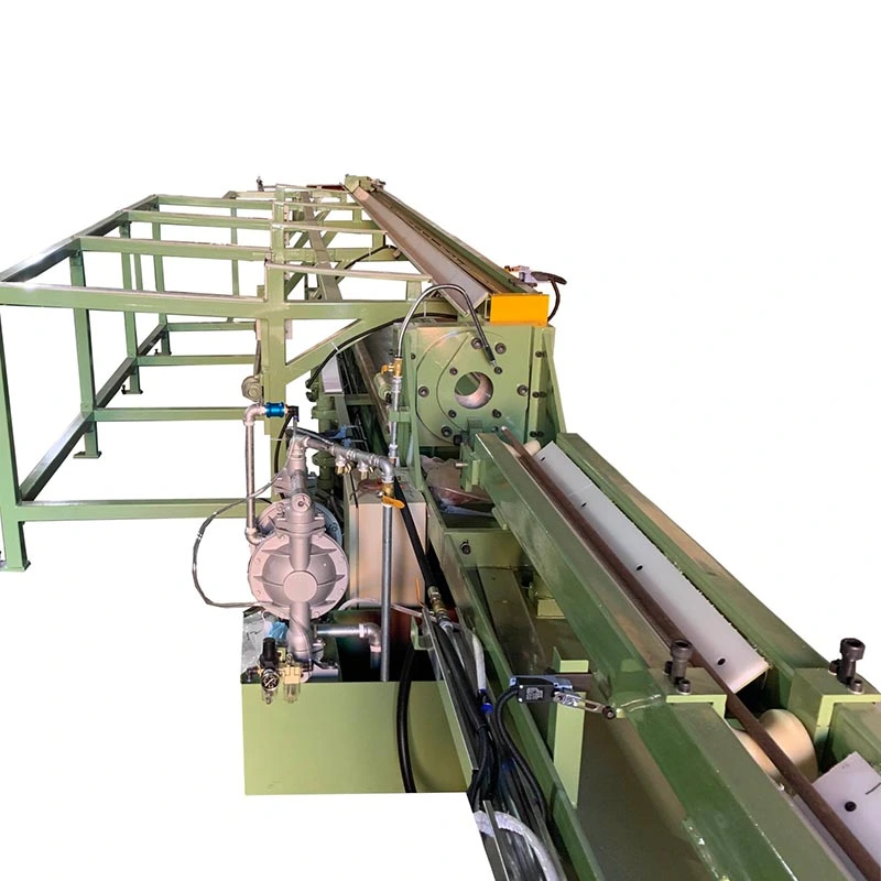
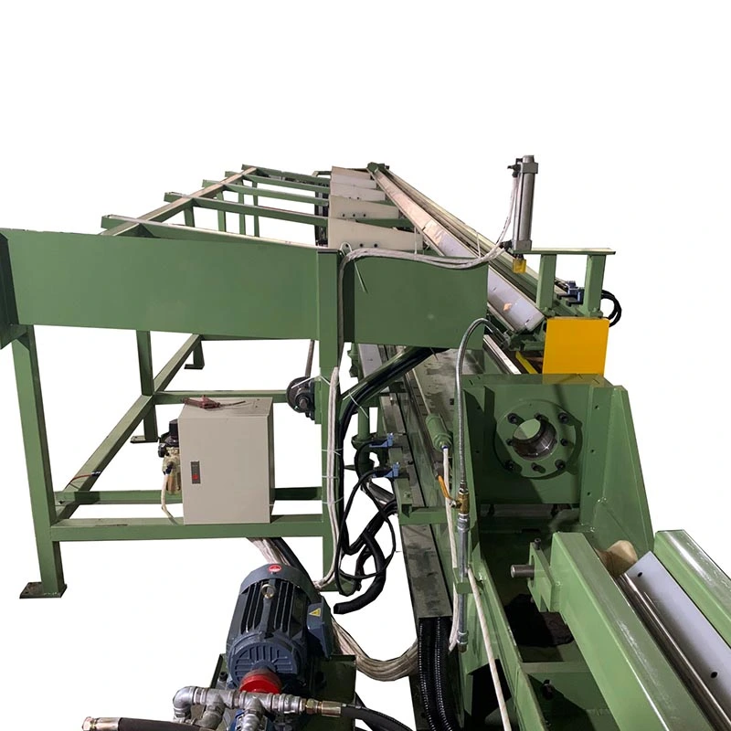
The tube is positioned at the drawing station and its prepared end is passed through the die. Depending on the process, a plug or mandrel is positioned inside the tube. The hydraulic cylinder then pulls the tube through the tooling at a controlled speed.
The main advantage of the hydraulic drive is that drawing speed and hydraulic pressure can be adjusted to suit different tube sizes and materials. This is useful when a production line handles more than one tube specification or when the drawing schedule requires different operating conditions between passes.
A prestressed closed frame supports the die, carriage, cylinder, and related components. Maintaining the relationship between the tube axis, die axis, and mandrel axis is important because misalignment can affect wall thickness, ovality, and surface quality.
The tube is drawn through the die without an internal plug. This method has a simpler tooling arrangement and is suitable when the main requirement is outside diameter reduction rather than tight control of the internal diameter and wall thickness.
A stationary plug controls the internal diameter during drawing. It is commonly selected when both outside diameter and wall thickness need to be controlled more closely than with sinking drawing.
The plug is positioned inside the tube and moves with the drawing process. The method can provide a different balance between reduction, internal dimensional control, and drawing force, so tooling selection should be based on the actual tube specification.
A long mandrel passes through the tube during drawing and provides greater control over the internal diameter and wall thickness. It is generally considered when internal dimensional requirements are more demanding.
The four methods are not interchangeable for every tube. Material strength, starting dimensions, finished dimensions, reduction per pass, lubrication, and required tolerances should be reviewed before selecting the tooling arrangement.
Drawing force is not selected by tube diameter alone. Two tubes with the same outside diameter can require very different machine capacities because of differences in material strength, wall thickness, reduction, tooling, and lubrication.
Carbon steel, stainless steel, alloy steel, copper, aluminum, brass, titanium, and other metals have different deformation characteristics. Higher-strength materials or heavier reductions generally require greater drawing force and a suitable tooling arrangement.
Incoming outside diameter, wall thickness, finished outside diameter, finished wall thickness, and tube length determine the reduction required from each pass. These values are needed before the machine model and tooling can be finalized.
The effective finished-pipe length varies by machine model. If the production line handles long tubes, the available drawing stroke and machine layout should be checked together rather than selecting the drawbench from force capacity alone.
Drawing speed affects cycle time, but maximum speed is not necessarily the best production setting for every tube. Material behavior, lubrication, tooling, reduction, and surface requirements can determine the practical operating speed.
The Pipe Hydraulic Cold Drawing Machine can be configured around the required operating method and production volume. PLC and HMI controls manage the drawing sequence, carriage movement, return stroke, operating parameters, and machine status. Additional tube handling equipment can be considered when loading, unloading, or repeated production cycles create a bottleneck.
FangRong supplies hydraulic drawbenches in different force classes. The table below shows the supplied FR series data. Actual configuration should be confirmed against the customer's tube material, dimensions, drawing method, and production requirements.
| Model | FR-2T | FR-5T | FR-10T | FR-15T | FR-20T | FR-30T | FR-50T | FR-70T |
| Max. Drawing Force (kN) | 20 | 50 | 100 | 150 | 200 | 300 | 500 | 700 |
| Drawing Speed (m/min) | 0~10 | 3~10 | 3~10 | 3~10 | 3~10 | 3~10 | 2~10 | 10~16 |
| Effective Length of Finished Pipe (m) | 6 | 5 | 5 | 9 | 5 | 5 | 7 | 9 |
| Finished Pipe OD Range (mm) | φ5 max | φ25 max | φ50 max | φ60 max | φ70 max | φ30~φ80 | φ30~φ100 | φ30~φ100 |
| Max. Finished Pipe Wall Thickness (mm) | 1.5 | 2 | 3 | 4 | 5 | 6 | 8 | 10 |
| Main Oil Cylinder (mm) | φ63*φ35 | φ80*φ45 | φ125*φ70*3200 | φ125*φ70 | φ150 | φ180*φ90*3000 | φ200*φ100 | φ280*φ150*9000 |
| Number of Hydraulic Stations | 1 | 1 | 1 | 1 | 1 | 1 | 1 | 2 |
| Working Pressure (MPa) | 21 | 21 | 21 | 21 | 21 | 26 | 26 | 26 |
| Max. System Pressure (MPa) | 26.0 | 26.0 | 26.0 | 26.0 | 26.0 | 31.5 | 31.5 | 31.5 |
| Main Oil Pump (Manual Variable Plunger Pump) | 40 | 40 | 40 | 50 | 50 | 50 | 50 | 50 |
| Main Motor (kW) | 3.7 | 7.5 | 22 | 30 | 45 | 75 | 75 | 132*2 |
| Outline Dimensions W×H×L (m) | 1.6*1.4*30 | 1.6*1.4*30 | 1.6*1.4*30 | 1.6*1.4*30 | 1.6*1.4*30 | 1.1*1.2*20 | 1.2*1.3*25 | 1.3*1.4*25 |
| Weight (t) | 2 | 3 | 5 | 8 | 10 | 15 | 20 | 30 |
Specification note: The above values are from the supplied FR model table and are provided for reference. Final machine dimensions, force capacity, tooling, hydraulic configuration, and operating parameters are confirmed according to the actual tube process.
Cold drawing can be used to control the outside diameter, wall thickness, and internal dimensions of tubes used for cylinder barrels and related components. The required drawing method depends on the dimensional requirements before honing or machining.
The Pipe Hydraulic Cold Drawing Machine can process steel tubes for mechanical components, industrial equipment, structural parts, heat exchangers, and other applications requiring controlled tube dimensions.
Copper and brass tubes can be drawn for dimensional control in HVAC, refrigeration, heat exchangers, plumbing components, and electrical applications. The appropriate tooling and drawing speed depend on the material and tube specification.
Aluminum tube drawing is used where controlled dimensions and lightweight tubular sections are required, including selected automotive, heat exchanger, and industrial applications.
Titanium, nickel alloys, and other specialty metals require process parameters matched to their strength and deformation behavior. The machine capacity, drawing method, tooling, and reduction schedule should therefore be confirmed from the actual material grade and tube dimensions.
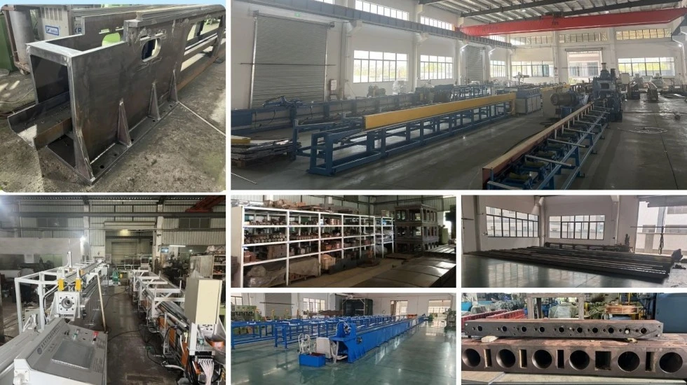
Before fabrication, FangRong reviews the tube material, incoming dimensions, finished dimensions, drawing method, reduction requirements, tube length, drawing force, and production target. These parameters determine the hydraulic system, cylinder capacity, tooling arrangement, machine stroke, and control configuration.
The machine frame, guide rails, drawing carriage, cylinder mounting structure, and die holder are machined and assembled according to the equipment design. Guide rail alignment is checked because the movement of the carriage directly affects the relationship between the tube and drawing tooling.
The hydraulic power unit, main cylinder, valves, pipelines, and related components are checked during assembly and commissioning. Hydraulic pressure, cylinder movement, valve response, and operating stability are included in the machine test.
The control system is configured for the agreed machine functions. PLC logic and HMI settings cover drawing operation, carriage movement, return stroke, operating modes, and relevant machine status information.
The completed machine undergoes no-load operation followed by load testing according to the agreed technical requirements. Mechanical movement, hydraulic performance, electrical controls, drawing functions, and safety-related functions are checked before shipment.
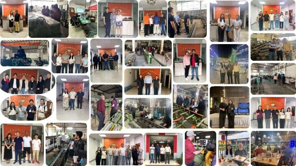
FangRong has been engaged in cold drawing equipment manufacturing since 1998. Its equipment range covers hydraulic cold drawing machines together with related tube and bar processing equipment.
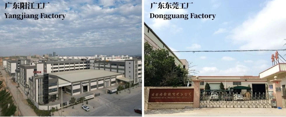
The company operates manufacturing facilities in Dongguan and Yangjiang, Guangdong, with production covering mechanical fabrication, machining, hydraulic assembly, electrical integration, machine assembly, and testing. Annual production capacity exceeds 650 machines.
For projects requiring more than a drawbench, the production line can be planned around processes such as pointing, drawing, straightening, cutting, and chamfering according to the finished tube requirements.

FangRong's quality management system is certified to ISO 9001:2015, Certificate No. UQ231211R1.
The Pipe Hydraulic Cold Drawing Machine is supplied with CE marking based on the applicable Machinery Directive 2006/42/EC requirements. The final safety configuration is confirmed according to the machine design and destination market.
SGS inspection can provide an additional independent inspection option for customers requiring third-party verification before shipment.
FangRong reports more than 130 patents, including 32 invention patents and more than 100 utility model patents. Representative patent numbers include 2013207829011, 2008300532117, and ZL2015 2 0842922.7.
For quotation and machine selection, customers should provide the tube material and grade, incoming OD and wall thickness, finished OD and wall thickness, tube length, required drawing method if known, expected production volume, and available workshop conditions.
MOQ: 1 set.
For quantity-based purchasing, quotation can be structured as follows:
1 set: Standard project quotation based on the selected model and configuration.
2–4 sets: Quantity-based pricing available after model and configuration confirmation.
5+ sets: Project or volume quotation based on the total equipment requirement.
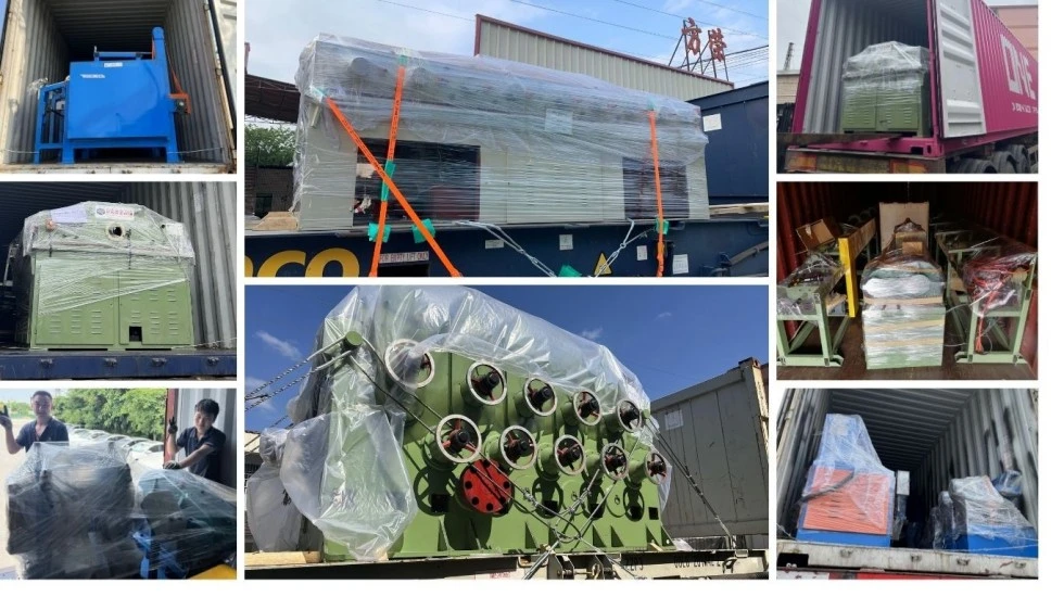
FOB China loading port. The specific departure port, packing arrangement, and shipping dimensions are confirmed in the commercial quotation according to the final machine configuration.
Standard order: approximately 30–60 days for FR-16 to FR-100 class equipment, subject to final configuration.
Large or customized order: approximately 90–120 days for larger models or projects involving special automation.
Expedited order: shorter delivery may be possible depending on production capacity and component availability. The confirmed delivery date should be stated in the order documents.
Payment: 30% deposit and 70% balance before shipment after factory acceptance testing (FAT).
Warranty: 12 months from commissioning, subject to the agreed warranty terms.
Start with the tube material, incoming OD and wall thickness, finished OD and wall thickness, tube length, required reduction, and production target. These parameters are used to determine the required drawing force, machine stroke, tooling method, and hydraulic configuration.
Sinking drawing uses no internal plug and mainly controls the outside diameter. Plug drawing introduces internal tooling to control the bore and wall thickness. Fixed plug, floating plug, and moving mandrel methods provide different levels of internal dimensional control.
Drawing force depends on material strength, tube dimensions, reduction area, die geometry, friction, lubrication, drawing speed, and the selected tooling. Therefore, tube OD alone is not sufficient for determining machine capacity.
Yes, provided the Pipe Hydraulic Cold Drawing Machine capacity and tooling are suitable. Carbon steel, stainless steel, copper, aluminum, brass, titanium, and other alloys can require different drawing parameters, tooling, and reduction schedules.
The number of passes depends on the total reduction, material properties, allowable reduction per pass, drawing method, and final dimensions. Larger total reductions are normally divided into multiple passes to keep the process within suitable forming conditions.
Yes. Depending on the finished product, the drawing machine can be combined with processes such as pointing, straightening, cutting, and chamfering. The line configuration should be determined from the required production flow and tube handling method.
They can be processed when the weld quality, tube condition, material, dimensions, and required reduction are suitable for cold drawing. The incoming tube condition should be reviewed before confirming the drawing process.
Provide the tube material and grade, incoming OD and wall thickness, finished OD and wall thickness, tube length, drawing method if known, required output, number of passes if established, and automation requirements. Workshop dimensions and power supply information are also useful for final machine planning.
Address
NO.163,Shatong Road,Shabu 2nd Industrial Zone, Dalang Town, Dongguan City, Guangdong, China