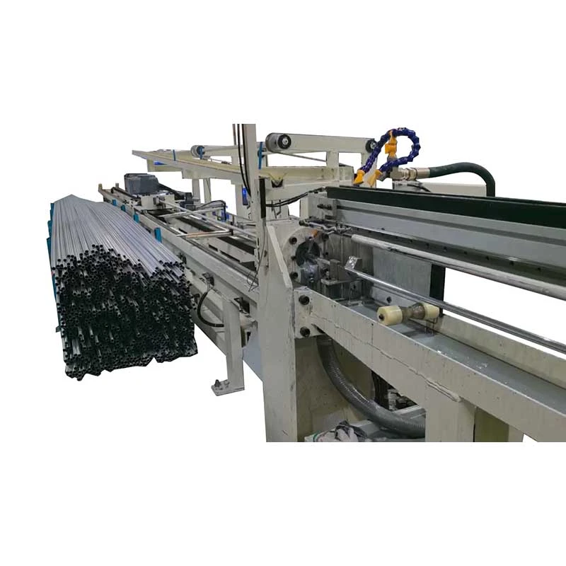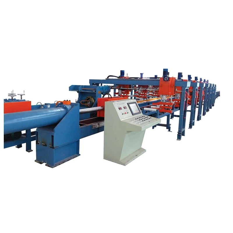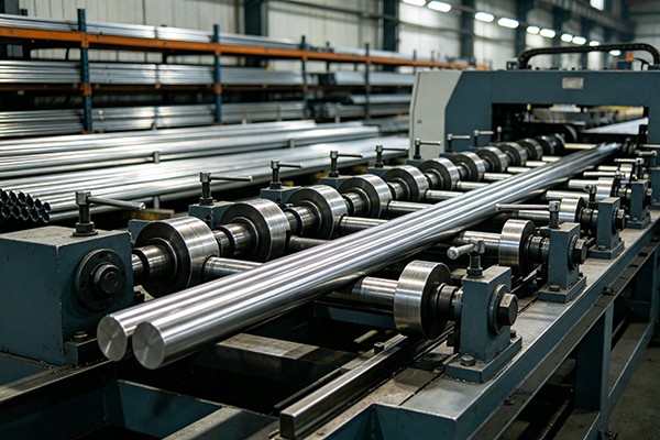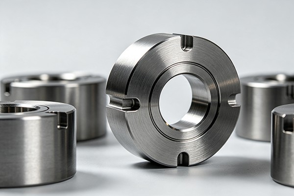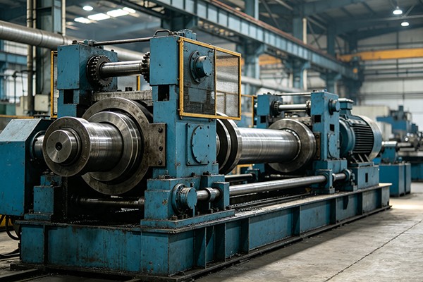

We offer a comprehensive range of precision metal processing equipment, including straightening, cold drawing, pointing, chamfering, cutting, thread rolling machines, and drawing dies, tailored for tube, bar, and wire materials across diverse industries.
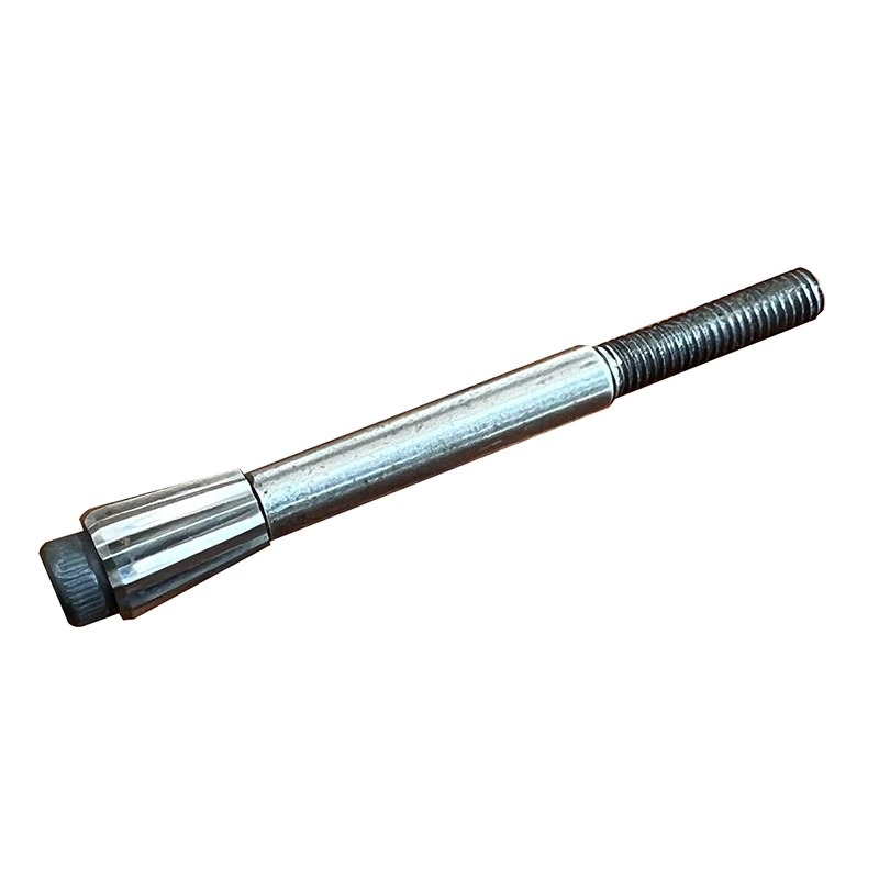
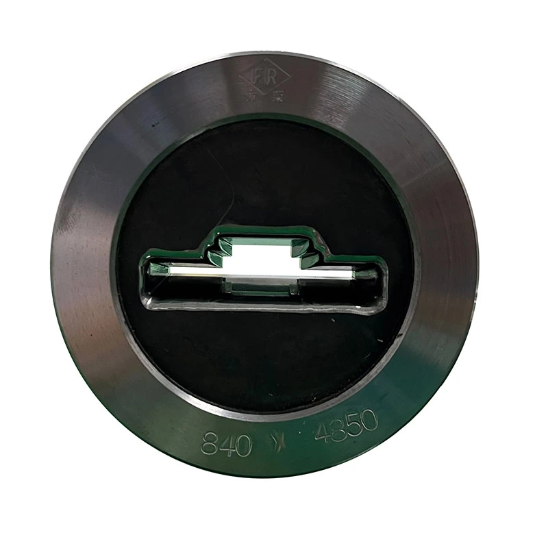
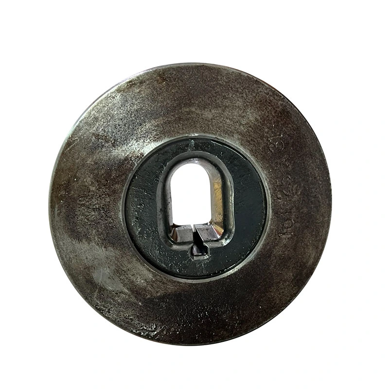
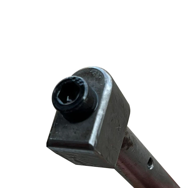
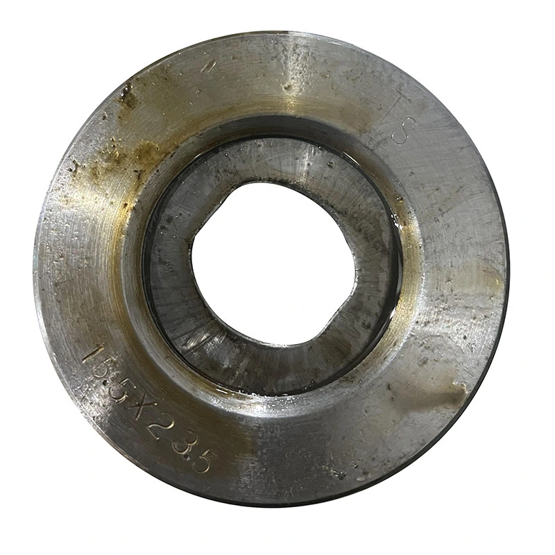
Drawing dies are precision forming tools used to reduce the cross-section of metal tubes, bars, rods, and wires while controlling the finished diameter, profile, and surface condition. Instead of removing material by cutting, the workpiece is pulled through a smaller die opening, causing controlled plastic deformation.
Tungsten Steel Dies and Diamond Dies are two major tooling options used in cold drawing. In technical terms, most products marketed as tungsten steel dies are made from cemented tungsten carbide, while diamond dies use natural diamond, polycrystalline diamond (PCD), or a diamond-coated substrate. The appropriate choice depends on the workpiece material, reduction per pass, drawing speed, lubrication, dimensional tolerance, and expected production volume.
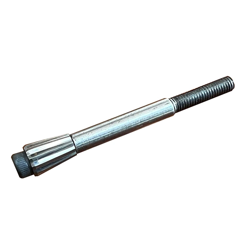
The die opening is not simply a hole with a fixed diameter. Its internal geometry determines how the material enters the die, undergoes reduction, contacts the bearing surface, and exits the tool. A small change in the approach angle, bearing length, or finished opening can affect drawing force, surface finish, dimensional stability, and die wear.
A typical drawing die contains several functional zones:
The exact geometry should be selected according to the material, reduction ratio, workpiece size, lubrication system, and drawing speed rather than copied from a standard die without considering the process.
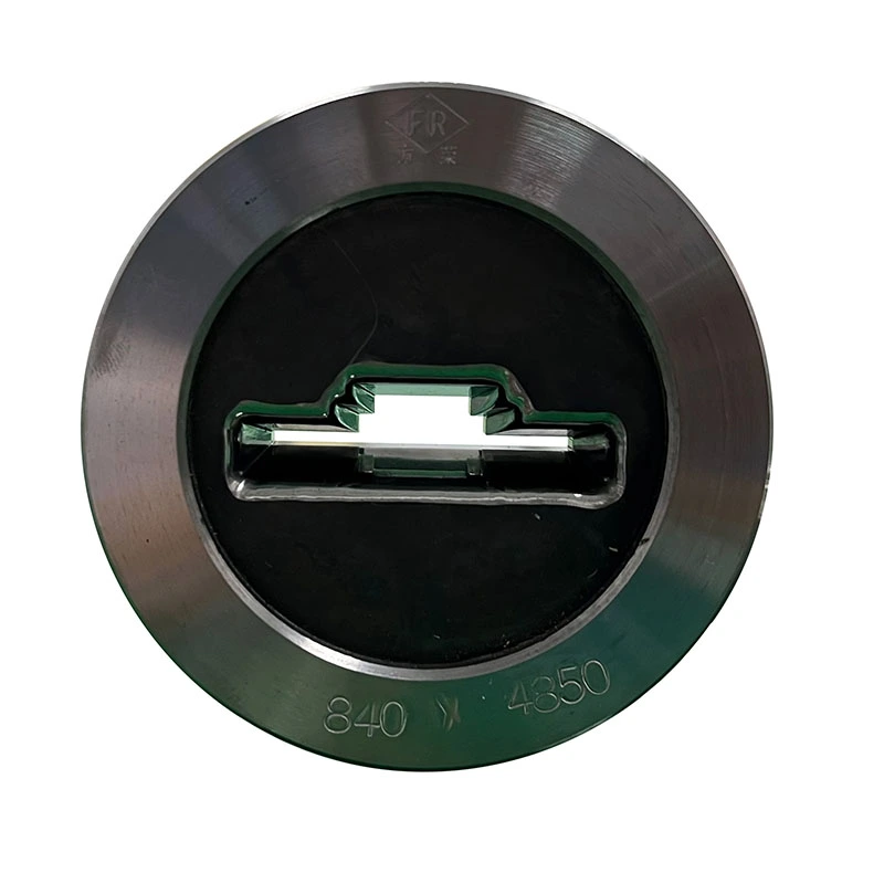
Tungsten carbide drawing dies are manufactured from cemented carbide, normally consisting of tungsten carbide particles bonded with a metallic binder such as cobalt. Grades such as YG6 and YG8 are commonly used in carbide tooling, although the appropriate grade depends on the drawing material and operating conditions.
Carbide provides a practical combination of hardness, wear resistance, compressive strength, and manufacturing cost. It is widely used for general-purpose tube, bar, rod, and wire drawing, particularly where the process does not justify the higher cost of a diamond working surface.
Typical carbide die selection factors include:
Carbide grades should not be selected by hardness alone. Increasing binder content can change toughness and wear behavior, so the die grade needs to match the actual combination of load, material, and drawing conditions.
Diamond dies use a diamond working zone where very high hardness and wear resistance are required. Depending on the application, the working element may be natural diamond, PCD, or a CVD diamond coating. These constructions are particularly relevant when die wear, dimensional drift, or surface quality becomes a major production concern.
Compared with conventional carbide tooling, diamond dies require a higher initial tooling investment, so their value should be evaluated against production volume, permissible dimensional variation, die replacement frequency, and the value of the drawn product.
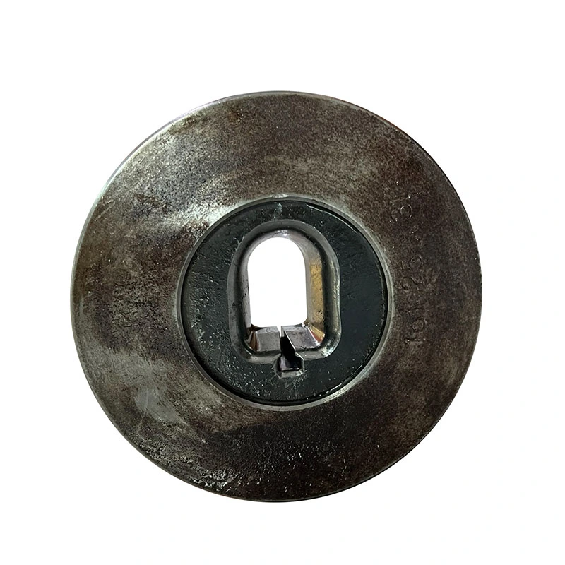
Polycrystalline diamond is produced from diamond particles consolidated into a working body, commonly supported by a cemented carbide substrate. The multiple-crystal structure provides a combination of wear resistance and practical mechanical strength.
PCD is often considered for continuous production where carbide wear becomes a limiting factor. It can be used for copper, aluminum, selected steel and alloy wire applications, and other processes where the drawing conditions are compatible with the PCD grade and geometry.
Natural diamond dies use a selected single diamond as the working element. They are traditionally associated with fine and precision wire drawing where a very smooth, accurately finished bearing surface is required.
The available stone size and geometry can limit the practical application of natural diamond for larger openings. For this reason, natural diamond is more commonly considered where the finished product has a high value or where fine dimensional and surface requirements justify the tooling cost.
CVD diamond dies use a substrate, commonly cemented carbide, with a diamond layer deposited onto the working surface through chemical vapor deposition. The technology allows a diamond working surface to be formed on a larger or differently constructed substrate rather than relying entirely on a natural diamond element.
CVD diamond coatings have been studied for drawing applications because the diamond surface can provide high wear resistance and favorable tribological characteristics. However, coating adhesion, substrate preparation, coating thickness, bore geometry, and final polishing all affect the finished tool, so CVD should be evaluated according to the specific drawing process rather than treated as a universal replacement for carbide or other diamond dies.
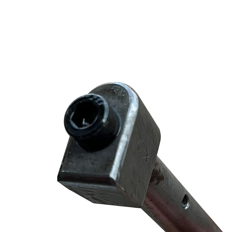
The choice between Tungsten Steel Dies and Diamond Dies should start with the production problem rather than the die material itself. A carbide die may be the more appropriate option for general-purpose drawing, frequent size changes, trial production, or processes where tooling cost is a major consideration. A diamond-based die becomes more attractive when wear resistance, dimensional stability, surface requirements, or long production runs justify the additional tooling investment.
| Die Type | Main Characteristics | Typical Considerations |
|---|---|---|
| Tungsten Carbide | Hard, wear-resistant, relatively economical | General-purpose tube, bar, rod, and wire drawing |
| PCD | High wear resistance and dimensional stability | Long production runs and applications where carbide wear is significant |
| Natural Diamond | Very fine, stable working surface | Fine wire and applications with demanding surface and dimensional requirements |
| CVD Diamond Coated | Diamond working layer on a substrate | Applications requiring a diamond surface with a coated die construction |
There is no single die material that is best for every drawing operation. For example, selecting a diamond die for a low-volume process with frequent diameter changes may not provide a meaningful production advantage, while using a conventional carbide die in a high-volume fine-wire application may result in excessive wear and dimensional drift.
For accurate die design, the die supplier needs more than the finished diameter. The following process information is normally required:
| Parameter | Why It Matters |
|---|---|
| Workpiece material | Determines deformation behavior, die loading, wear mechanism, and suitable die material |
| Incoming size | Used to determine the required reduction and die opening |
| Finished size | Defines the target bearing diameter and dimensional tolerance |
| Reduction per pass | Directly affects drawing force, heat generation, and die loading |
| Drawing speed | Influences friction, temperature, lubricant behavior, and wear |
| Lubrication | Affects friction, surface finish, drawing force, and tool life |
| Required tolerance | Determines the bearing design and finishing requirements |
| Surface requirement | Helps determine working-surface material and polishing specification |
For existing production lines, supplying the current die drawing, worn die dimensions, sample workpieces, and actual drawing parameters can further improve the accuracy of replacement die design.
Tube drawing requires control of both the outside diameter and, depending on the process, the inside diameter. Different tube drawing methods may use a die alone, a fixed plug, a floating plug, or other internal tooling arrangements. The die geometry therefore needs to be matched to the complete tube-drawing process rather than selected only from the finished outside diameter.
Important factors include tube material, wall thickness, incoming OD and ID, reduction per pass, mandrel or plug configuration, lubricant, and required dimensional tolerance.
Bar and rod drawing generally involves solid cross-sections, so the die controls the reduction from the incoming diameter or profile to the finished size. The required die material depends on the alloy, hardness, reduction schedule, drawing force, and production volume.
For carbon steel, stainless steel, copper, aluminum, and specialty alloys, die geometry should be developed around the actual material behavior. A die designed for a soft non-ferrous alloy should not simply be copied for a higher-strength steel application.
Wire drawing places greater emphasis on bearing quality, surface finish, dimensional consistency, and wear because small changes in the die opening can affect the finished wire diameter. For fine and high-volume wire production, PCD, natural diamond, and CVD diamond-coated constructions may be considered alongside conventional carbide dies.
For multi-pass wire drawing, die selection should also be considered as part of the complete pass schedule. The reduction assigned to each die, incoming wire condition, lubrication, drawing speed, and cooling can influence the actual performance of the tooling.
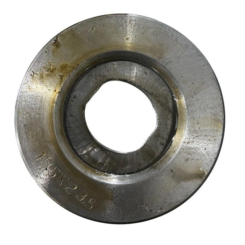
Not all drawing applications use round products. Drawing dies can be designed for square, rectangular, hexagonal, oval, sector, and other non-round profiles when the forming process and material allow it.
Shaped die design requires more than changing the final opening profile. Corner radius, reduction distribution, bearing length, entry geometry, material flow, and alignment all affect the finished profile. For complex sections, the die design should be developed from the actual incoming and finished dimensions rather than from a nominal shape name alone.
The manufacturing route depends on the selected die material and construction. A typical process includes material selection, blank preparation, rough machining, forming or sintering where applicable, precision grinding, bore finishing, polishing, casing or mounting, and final inspection.
For diamond and diamond-coated dies, additional attention is required for the working element, substrate preparation, bonding or coating condition, bore geometry, and final surface treatment.
Inspection records can be matched to the die identification number to support replacement ordering and production traceability.
Die wear normally develops gradually in the working zone. Common signs include an increase in finished diameter, loss of dimensional consistency, scratches on the drawn product, changes in drawing force, or visible wear in the bearing area.
When the die construction allows regrinding or repolishing, the decision should be based on the remaining die geometry and the required finished size. Simply polishing a worn die without restoring the correct geometry may not solve dimensional or surface problems.
Proper alignment, clean incoming material, effective lubrication, and control of drawing parameters are equally important. Even a high-wear-resistance die can experience premature damage if the workpiece enters the die off-center, carries scale or contamination, or operates under unsuitable lubrication conditions.
Tungsten Steel Dies and Diamond Dies should not be compared only by purchase price or nominal hardness. The more useful comparison is how each die performs under the actual combination of material, reduction, speed, lubrication, tolerance, and production volume.
For a short production run, carbide may provide sufficient service life without unnecessary tooling investment. For continuous production where frequent die replacement causes downtime or dimensional drift, PCD or another diamond-based construction may provide a stronger economic case. The correct decision depends on measurable production conditions rather than a general claim that one material is always superior.
FangRong has more than 26 years of cold drawing equipment and process engineering experience, supporting applications involving tube, bar, rod, and wire drawing. Drawing dies are developed in connection with the drawing process, including the incoming material, reduction schedule, finished dimensions, and machine conditions.
Our two manufacturing facilities support machining, assembly, testing, and technical development for cold drawing equipment and related tooling. Die specifications can be developed from customer drawings, existing die samples, workpiece dimensions, or actual production requirements.
Where the application is difficult to define from drawings alone, production samples can be used to verify die geometry and process requirements before final production.

Our manufacturing workflow includes engineering review, material inspection, machining, precision finishing, assembly where required, dimensional inspection, and final quality checks.
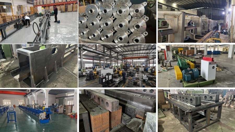
Quality control focuses on the dimensions and working geometry that directly affect drawing performance. For customized dies, the final inspection is matched against the approved drawing or technical specification before shipment.

FangRong operates under an ISO 9001:2015 quality management system and has obtained CE and SGS-related certifications and inspection documentation for applicable equipment. The company also holds national patents covering its machinery and engineering technologies.
These equipment certifications should not be interpreted as certification of every individual drawing die. For tooling orders, material grade, dimensional inspection, geometry, and customer-specific technical requirements are the relevant quality criteria.
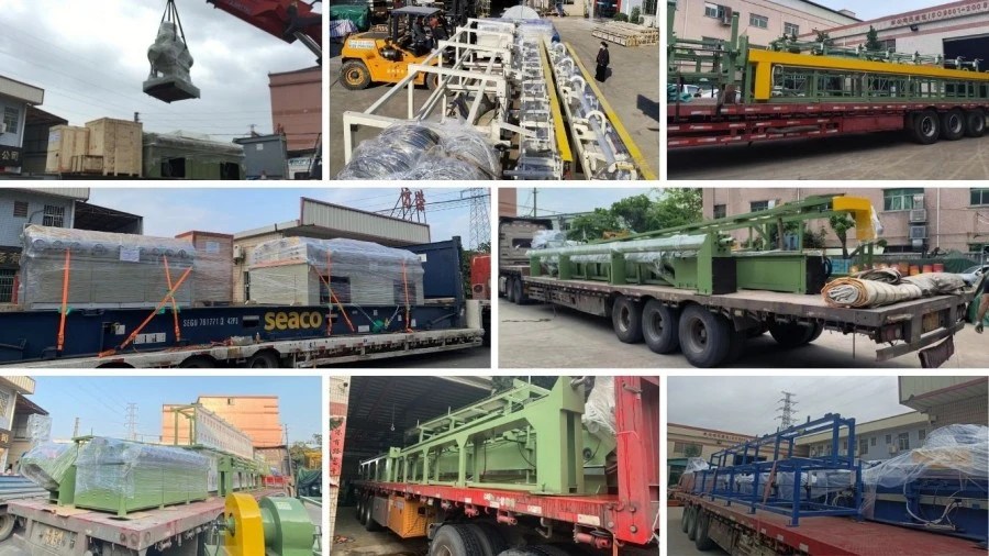
Drawing dies are packaged according to their size, construction, and sensitivity of the working surface. Precision working areas are protected against impact, contamination, and moisture during transportation. Export packing can be arranged for individual dies, tooling sets, or combined equipment orders.
Tungsten carbide provides a practical combination of hardness, wear resistance, toughness, and tooling cost for many general drawing applications. Diamond dies generally provide higher wear resistance and are considered when production volume, fine dimensional control, or surface requirements justify the higher tooling cost.
Both carbide and diamond-based dies can be used for copper and aluminum. The selection depends on alloy, hardness, reduction, drawing speed, lubrication, finished tolerance, and production volume. PCD and other diamond constructions are often considered when wear or dimensional drift becomes a significant production issue.
Yes. Drawing dies can be designed for square, rectangular, hexagonal, oval, sector, and other custom profiles. The customer should provide the incoming profile, finished profile, material, reduction schedule, and tolerance requirements so the die geometry can be developed correctly.
The choice depends mainly on wire size, required surface and dimensional performance, production volume, and tooling budget. Natural diamond can be advantageous for fine precision applications, while PCD offers a different combination of wear resistance, construction flexibility, and production economics. The actual application should be reviewed before selecting the die type.
Please provide the material grade, incoming and finished dimensions, tolerance, reduction per pass, drawing speed, lubrication method, die type if known, and application. A drawing or sample of the existing die is also useful, particularly when replacing worn tooling.
There is no fixed service-life figure that applies to every die. Wear depends on the workpiece material, reduction, speed, lubrication, alignment, incoming surface condition, die material, and required dimensional tolerance. Actual wear should be monitored through finished-product dimensions and working-surface inspection.
Some carbide and diamond-based dies can be reground or repolished, depending on their construction and remaining working material. The new bore size and geometry must be controlled during reconditioning; otherwise, the die may continue to produce dimensional or surface problems.
Yes. Die geometry is closely related to the drawing process. When the die is supplied together with a cold drawbench or drawing line, we can review the workpiece dimensions, reduction schedule, drawing force, speed, tooling arrangement, and required finished tolerance as one process rather than treating the die as an isolated component.
Address
NO.163,Shatong Road,Shabu 2nd Industrial Zone, Dalang Town, Dongguan City, Guangdong, China